Help with a replacement SB23NRXS45-8 8 Inch driver

Hi everyone,

Would someone be kind enough to help me,

I am replacing the 8 inch drivers in my dynaudio profile 3 speakers ( Driver 21W54 ) with the SB23NRXS45-8
They mate to a Dynaudio D54AF dome midrange
The crossover network as all first order with the inductor to the bass driver 1.8 MH Crossover point 700 HZ
I obviously need to keep that inductor and crossover point for integration to the midrange.
The original bass driver had no cone breakup filter on it but my question is the new replacement SB23NRXS45-8 driver will .
The cone breakup un the graph looks to be between 1000HZ to 4000 HZ
Can someone please point me in the right direction to calculate a notch filter for this driver.

Regards

Any DIY designs using BD332~BD338

Hi, I found a bunch of these transistors, namely BD334 and BD333 , but I see I can also purchase the other variants easily.
Are there any interesting amplifiers made with these darlington transistors? I have some headphones id like to make an amplifier for (8ohm and 120ohm over-ear models).

Attachments

Composite amplifier with balanced inputs LM3886 TINA-TI simulation

This is just me having too much fun with TINA-TI simulator 🙂

sch.PNG


I don't know if it will work in the real world (might build it just to tinker around)

In the schematics I am using LM4562 and LM3886 as composite amplifier. That usage probably has problems since I don't know much about composite amplifiers.

What I am curious about is that LM4562 OPAMP used not only as a part of a composite amplifier, but also as a differential amplifier for balanced input signals from the previous stage.

Any comments are appreciated!

Attached is the simulation file and screenshots for frequency and phase response.

PS: I am aware that @tomchr has built excellent composite amps and I am considering building one of those in the future. But for now I am just having fun tinkering with the design concepts...

Attachments

  • freq.PNG
    freq.PNG
    15.8 KB · Views: 239
  • phase.PNG
    phase.PNG
    14.5 KB · Views: 198
  • sch-composite-bal.zip
    sch-composite-bal.zip
    10.9 KB · Views: 93
  • tr.PNG
    tr.PNG
    13.8 KB · Views: 230

SB Acoustic full range driver in Transmission Line

Hello everyone, I am from Indonesia and newbie to DIY audio enthusiast, actually vacum for around 25 years after working as an employee.
Now just retired, looks like there are challenging in design of Transmission Line box with full range driver especially SB Acoustic produced in Surabaya, Indonesia has launched SB Acoustic SB20FRPC30-8 8 inch.

Is there any software running in Mac OS, using Macbook Air M2 to design & test Transmission Line box and what kind tools supporting?
Or anybody has built Transmission Line box with this driver, any link video test sound?

I have its detail specification from factory.

Thank you everyone.

Erin's Audio Corner (my new site/YouTube page)

Mods: I don't *think* this violates any rules but if it does and needs to be removed, please let me know how I can still share this info since I think many here will be interested in it.

Many of you know that I used to do speaker/driver testing for a number of years for DIYMA before moving on to creating my own site (medleysmusings). If you have no idea what that is, it’s a site I used to post objective data to and share with the community. It was focused on providing Klippel data, frequency response (on and off-axis) as well as THD and a few other things along with analysis for various speaker drive units. I took the last couple years off due to personal reasons. But I'm gearing back up to do something big, at least for me. I’ve been itching to change things up and move my review format to YouTube and also expand out of raw driver testing and instead provide a wider range of information. So, that's what I'm doing.

The core of my efforts will focus on product reviews and tutorials (i.e., how to use a DSP, how to tune, what to listen for, etc) along with some other miscellaneous things. I will continue to provide objective data when I can/where it makes sense and I plan to do that as a supplement to the YouTube format; providing the data via a new website. I have a long list of ideas that I’ve collected over years. I think I have a few ideas for my reviews you all will really dig.

I have created a Facebook Group page for those who want to follow it. This page will be a way for me to update everyone on progress I make toward completing reviews. If I get a new piece of hardware to test I’ll share it. Links will be posted to reviews. That sort of stuff. It’ll be an extension of my YouTube review page because, frankly, it’s easier to support conversation here than it is on YouTube. Here’s the link: Log into Facebook | Facebook

To be entirely transparent, I hope to be ad-driven at some point and also do some affiliate marketing (i.e., Amazon, Parts-Express, etc) so I can use some of the advertising revenue toward purchasing new test equipment and products to test/review. I don’t see me ever actually making money; breaking even would be nice. I’ve already sunk nearly a grand in to what I need to get going. In order to get to the point where I can monetize videos through YouTube, however, I’ll need to hit 1k subscribers, and some crazy number of hours viewed per month. So, I ask you all, if you are interested in any of the stuff I’ve done and the past or you just want to support what I’m doing, go ahead to my YouTube page and click the subscribe button. I don’t have anything out there at this moment in the way of reviews but I’m already working on some really, really cool stuff. And if you are interested in the items I review in the future, feel free to click any links I provide to my affiliate advertisers so I can get a small percentage of the purchase fee (hey, you were gonna buy it anyway). All that helps me keep this thing rolling and keep me from going in debt in the process.

Here’s a link to my YouTube page:
YouTube

And that’s it… I just ask you to bear with me. I’m not a video editor so I don’t expect to knock this stuff out of the park my first few attempts. But over time, with your feedback, I will hopefully improve the final product and provide an entertaining and educational set of videos. 🙂

Thanks,

Erin

Schematic hunt: RIAA Phono Preamp

I've wanted to build an amplifier for quite a while. Initially from the guitar amplifier side, and more recently from a hifi perspective. As I look around, I feel like it should be easier than it is to find something meeting my needs, but I keep coming up empty. I want to build an all tube (including power supply) RIAA phono preamp. I want to use all readily available and currently produced tubes. Coming from the guitar amplifier perspective, to me this mostly means 12AX7/5U4, but I'm not 100% aware of everything in current production. I just know I can hop on down to GC, and pick up those tubes brand new and reasonable quality all day long. Call it future proofing.

Can anyone point me in the direction of a schematic or set of schematics from wall to input to output for such an amplifier? Thanks.

Socket in Teflon for EL3N-AZ1-AD1-AZ4 ecc. CNC built

Hi, I designed and built these fantastic sockets, in PTFE, for my EL3N amplifier, my job consists in making precision prototypes for the most varied industrial sectors, so I decided to make them available to all passionate DIYers like me , there are unfortunately several hours of work, with these but the quality justifies the effort.
I'm selling them for 95 euro cad.
WP_20221205_16_17_18_Pro.jpg
WP_20221205_13_26_43_Pro.jpg
WP_20221205_13_28_18_Pro.jpg
WP_20221205_16_11_20_Pro.jpg
WP_20221219_21_39_59_Pro.jpg


Maurizio
e mail. maurimauricap@ gmail.com from Italy

EL84 Plate Dissipation

I just finished an EL84 push-pull amplifier using Electro-Harmonix (EL84EH) tubes. I'm running 300V B+ and a shared bypassed 110 Ohms cathode resistor. Each EL84 also has it's own 2 Ohm (unbypassed) cathode resistor to measure bias current, and I'm using a 10 Ohm potentiometer to adjust the bias balance between the two tubes. Total, each EL84 has 117 Ohms cathode resistance.

This results in about 47mA bias current per tube, making the plate dissipation around 13.5 Watts. This is a little higher than the rated 12W.

Are the EL84EH capable of this plate dissipation, or should I adjust the plate current down a little bit (i.e. 43mA)?

Exicon Mosfets

I have an "Opus" amp on the operating table with a broken mosfet. It is an Exicon 10P20 (10a 200v TO3 package). I have 10P16 (not enough volts) and 20P20 (too many amps) in stock and hoardes of Hitachi J56/K176 which DONT play nice with Exicons (they need to have the same amount of oar in the water as 5 others). Anyone know where I can find the (no longer made) Exicons?.

Opamp overshoot (w/screen pics)

Hello all,

I "upgraded" two quad opamps in a simple 4 channel synth mixer.
TL074c= out
AD8513 = in
(soic)

AD8513 datasheet.....LINK

I then checked for stability on my scope. I did not see "ringing" but did see "overshoot" at the transients, generally under 2kHz. Over 5kHz, they mostly even-out.
Here are two screenshots about 1kHz.
Yellow = source
Green = mixer output
(I made green's gain is a little higher for visual clarity)

SCR04.PNG
SCR03.PNG


Second one is the same, just zoomed-in.
Gain pot is around typical listening level, no load. Cables are short.

Here is the Mixer schematic...... https://github.com/pingdynasty/Mix/blob/master/hardware/LinearMixerRev04-schematic.pdf
Notes:
There is no overshoot out of the first-stage quad opamp, only out of the second quad opamp, at the output....before (or after) the 1k ohm output resistor.
I tried putting a snubber network on one output, as suggested by the AD8513 datasheet, with no affect at all.
I also added 0.1uf psu bypass caps on the affected quad opamp, before testing, as a precaution.
I added some 4 foot length cables to the output just to see what would happen.....no effect/difference.

Frankly, it "sounds" fine. Should I even worry about this ?

Measure cartridge response with a piezo disc?

Just a quick idea that came to my mind this evening. A couple of weeks ago I was using a cheap piezo disc, recycled from a broken smoke detector, to try and generate some ultrasonics up to 100kHz. The reason was to test a 1/4" microphone capsule with a quickly hacked together mic preamp for their suitability to capture the sounds of bats. I'm not quite satisfied with the results yet, but it kinda sorta worked okay for a first test. Of course there's a hen and egg problem here, since I neither know the frequency response of the mic, nor the piezo disc. The response was quite rough, but I was totally able to get up to the 96kHz recording limit of my sound card with no effort.

So now I thought about what might happen if I use this piezo disc instead of a vinyl test record, place the needle on top of it, and play a frequency sweep.

The piezo disc was connected directly to the output of the soundcard (a Scarlett 2i2) and excited full steam with -3dBFS output from Room Equation Wizard. The phono output went through a diy RIAA preamp connected back to the soundcard input and the following response recorded:

response.png


Looks pretty rough, but the part between 18k - 28k is somewhat interesting. It seems to suggest a useable response up to 23kHz without an early peek or drop.
My quick'n'dirty test setup is certainly far from ideal, but maybe there's some potential to achieve some better results? The main reason here would be to observe the range from 15k - 25k to fine tune the input capacitance of the preamp.

piezo-cartridge.jpg

LM338 10A power supply for 33V possible?

Looking for suggestions on the schematics that I came up with. Everything was based on the datasheet (almost).

I am anticipating each LM338 to produce [(35V-32V)*8A]/2 = 24W/2 = 12W of heat.

I found this heatsink here by Ohmite - https://www.mouser.com/ProductDetail/588-FA-T220-64E - hopefully this will be enough if I mount each regulator on its own heatsink.

I am also wondering what that 1uF el capacitor at the input is doing? Can I replace that with bigger capacitance one (10uF or 47uF)?

LM338-OPA990-10A.PNG


Here is what datasheet suggests:

datasheet-sch1.PNG


datasheet-sch2.PNG


Any suggestions and help are appreciated!!

XLR Question: Conductor Quality on + & -

Gents, I have an interesting scenario I'd like to run past you - I purchased a nicer silver conductor XLR cable a while ago, but here is the thing: The pin-2/+ Conductor is a beautiful solid core silver, but the cable itself is constructed with this one silver conductor with the other two comprising of 2 separate layers of silver plated braided sleeve. Pin-3/- is a conductor of lesser quality - with GND being fine, whatever.

With most equipment being differential, what might I be losing with a lesser quality conductor on the negative path? I was thinking of changing cables to one which has both pins 2&3 solid core silver, but in a differential setup internally within the components, would it matter?

Much of this is based on the clear audible differences and improvements from silver conductors to that of other material.

Thoughts?

Effect of multiple stacked short horns

Hello. I was wondering if anyone had documentation on summation of HF sources through short horns? Looking at the EAW Anya and similar HF arrays, they appear to be using several HF drivers stacked together with short conical horns instead of the typical line array waveguides.

When sources are within 1/4 wavelength or shorter they tend to sum more cohesively, right? But is that at the source or at the exit of a horn for the distance? It would appear that the Anya uses several short and slightly bent horns. I'm wondering if anyone has tried something similar. It would appear that the Anya has very little or no verticality in the horns and that every other one shifts horizontally as they are stacked.

Denon PMA QS10-II sound level not stable

Hi guys,

Maybe someone can drop me a hint to a solution on the following issue. Sound level from my Denon PMA QS10 mk 2 is not stable. Volume drops and rises again but it is hard to put a finger on when this occurs exactly. Quite anoying it is. Most of the time sound quality remains good but sometimes serious distortion can be heard when such a drop occurs, especially when it comes down from a higher soundlevel. It looks it is more sensative for this behavior at low volumes. Then also, more drops follow one after another. The amp has all new and original UHC-MOS components done by a professional technician. Have tried several loudspeaker arrangements, currently B&W 801-S3 (with refurbished tweeters, aka new ferro fluid added) in series with OLS (Kharma nowadays) with Van Den Hull cables. Tried all possible settings too, amp warm or cold, sound direct on/off etc. Amp too good to put on a shelf and make it a museum piece. Anyone idea's? Much appreciated, thanks for your time anyway. Best regards, Jan (Belgium)

Attachments

  • index.jpg
    index.jpg
    155.4 KB · Views: 78
  • index2.jpg
    index2.jpg
    160.8 KB · Views: 70

Dumb but Honest Question #1 -- conventions for spec descriptions

When buying parts for boards, BOMs will indicate specs for caps, resistors, etc. My question is: Are those specs meant to indicate the exact specs that should be bought, or are they mean to set out minimums?

For example: In a BOM i am working on ordering parts for, the values for the Caps are listed as 120u/25V.

The capacitance is 120u. Does that mean ONLY 120u, or is that a minimum?
25V -- is that ONLY buy a 25V cap, or does that mean 25V is the minimum?

Another example:
resistor spec is: .25W Film, 4.99K

Does that 4.99K value mean ONLY buy 4.99K resistors, or is there a range from that that is acceptable?

I am early going in this (obviously) and i have always assumed these specs meant ONLY. But I see discussions where people are talking about variations pretty freely, and so it makes me think that the specs are looser than might otherwise appear.

Bones
Lincoln, Nebraska

The Lab12 PA Subwoofer Smack Down/Death Match

The Eminence Lab12 has proven itself worthy in a variety of low-tuned PA applications. This venerable driver has held up well and is still a good candidate for many types subwoofer designs.

The Lab12 has been been around for a while and had been used in bass reflex, tapped horn, and front loaded horn alignments, so I propose a shoot-out of some of these Lab12 designs. Let's not get nasty. What is ideal for one person might not work for another, so please keep an open mind.

One of DIYaudio.com's elder statesmen, weltersys, has two proven designs that I submit for the first-round smack down.


In one corner we have the weltersys Keystone Sub, a tapped horn that is very adaptable:

http://www.diyaudio.com/forums/subwoofers/185588-keystone-sub-using-18-15-12-inch-speakers.html

They Keystone Sub is a big fella (45" tall x 26.5" wide x 22.5" deep), but loaded with two Lab12's goes low and LOUD. This is the grey race on the graph below.


In the other corner we have the weltersys Dual Lab12 bass reflex design:

FREE SUB PLAN: Dual Lab12 (Front Loaded) by Welter Systems

The Dual Lab12 is tiny little fella (22.5" high x 26.5" wide x 22.5" deep) - half the size of the Keystone Sub. It goes just as low as the Keystone, but not as loud. This is the blue trace on the graph below.


So, if you needed a subwoofer that went really low and load, which of these designs would you build, and WHY? What are the pro's/con's you see of each design.

Let's keep things civil. I personally think these are both excellent designs - one of my biggest arguments would be size and portability.

Attachments

  • WelterSys Keytone Sub.png
    WelterSys Keytone Sub.png
    271.1 KB · Views: 1,629
  • WelterSys Dual Lab12 Sub.jpg
    WelterSys Dual Lab12 Sub.jpg
    97.8 KB · Views: 2,744
  • WelterSys Lab12.png
    WelterSys Lab12.png
    70.4 KB · Views: 1,577
  • Like
Reactions: DblAA

FS $400 - Twistedpear Audio Kit BUFFALO-IIISE PRO (ES9038) DAC Complete and JLsounds I2SoverUSB v.III USB to I2S interface

SOLD NO LONGER AVAILABLE


I bought this complete kit and the great I2SoverUSB v.III interface and have decided I will never build this. Free US shipping, contact me for OUS.

Buffalo-IIIsePro38 Complete Kit Combo w Transformers
[1] Buffalo-IIIsePro38 2-Channel DAC w/Full Series Regulator Set
[1] Centaur 2A Power Supply Complete Kit
[1] Mercury Balanced I/V Stage v1.1 Kit
[1] Placid HD BP Power Supply Kit
[1] 9V+9V (30VA) Power Transformer
[1] 15V+15V (50VA) Power Transformer

Also I2SoverUSB v.III (see attached )
XMOS XU208 processor, USB update
Sampling frequencies: 44.1kHz, 48kHz, 88.2kHz, 96kHz, 176.4kHz, 192kHz,
352.8kHz, 384kHz, 705.6kHz and 768kHz
16-, 24- and 32-bit resolution
DSD64 - DSD512

Attachments

  • xform All Parts.jpg
    xform All Parts.jpg
    394 KB · Views: 143
  • TPA Order Centaur 9V xform.png
    TPA Order Centaur 9V xform.png
    15.5 KB · Views: 132
  • TPA Order Buf3 Mercury 15V xform.png
    TPA Order Buf3 Mercury 15V xform.png
    23.8 KB · Views: 129
  • TPA Buff IIISE Combo.png
    TPA Buff IIISE Combo.png
    14.8 KB · Views: 128
  • Thump Buster All Parts.jpg
    Thump Buster All Parts.jpg
    392.6 KB · Views: 117
  • Placid BP HD PS All Parts.jpg
    Placid BP HD PS All Parts.jpg
    356.1 KB · Views: 133
  • Placid BP HD board.jpg
    Placid BP HD board.jpg
    521.4 KB · Views: 133
  • OTTO All Parts.jpg
    OTTO All Parts.jpg
    327.5 KB · Views: 129
  • Mercury IV All Parts.jpg
    Mercury IV All Parts.jpg
    332.4 KB · Views: 169
  • I2SoverUSB-vIII - 1.jpg
    I2SoverUSB-vIII - 1.jpg
    334.5 KB · Views: 131
  • I2SoverUSB vIII Features.png
    I2SoverUSB vIII Features.png
    143.7 KB · Views: 153
  • I2SoverUSB vIII board.jpg
    I2SoverUSB vIII board.jpg
    579.6 KB · Views: 177
  • Centaur boxes.jpg
    Centaur boxes.jpg
    489 KB · Views: 155
  • Centaur All Parts.jpg
    Centaur All Parts.jpg
    358.8 KB · Views: 142
  • Buffalo-IIISE PRO-38.jpg
    Buffalo-IIISE PRO-38.jpg
    330.5 KB · Views: 144
  • Buffalo-IIISE Pro-38 PCB.jpg
    Buffalo-IIISE Pro-38 PCB.jpg
    445.3 KB · Views: 198

Introducing the bit "Teleporter"

Hello folks.

As many of you know I am working on a killer USB board and one of its features will be LVDS output of the PCM signals.

Well to support that I needed to test that it would actually work at the very high frequencies I was using. Well I am happy to report it absolutely does work, and extremely well!

In the process I created a little module that is also useful for many other applications. That module is call "Teleporter" and here is what it does:

  • It is a LVDS transceiver. It works in LVDS mode1 and mode 2. The LVDS channels are properly terminated.
  • It has both a .1" header and RJ45(for CAT5) connector.
  • It has an on-board low noise LT1763 regulator.
  • It has 4 independent LVDS transceiver channels that can each be configured as a transmitter or receiver.
  • Each channel either has TTL input (in transmit mode) or TTL output (in receive) mode.

You use two(or more) of these modules for a complete application. One at the source and one at the DAC or some other receiving device. They are designed to be panel mounted using 90deg tabs on the PCB. We will probably proved some with the kit.

NOTE: Please install (or short with solder) J1 for normal (type 1) operation where two teleporters are used as transmitter and receiver. Omitting J1 allows for type-2 receiver mode.
See section 3.2.3 here:

http://www.ti.com/lit/an/slla108a/slla108a.pdf

Here is how I have used it so far:

Also if your board has a J2 position - that jumper connects the jack shield to GND. It is recommended to close J2 if you use shielded CAT5/6.

- DSD/PCM output from a modded Denon SACD player to Buffalo III.
- USB audio to Buffalo III. (up to 384khz tested so far with 256fs master clock)

I have tested it carrying a signal up to 100Mhz(master clock) and it worked flawlessly so far. It *should* be able to handle up to 125Mhz, but I have not tested that yet.

We will be making these available very soon. They will be fairly inexpensive but I do not know the price just yet. Brian and I need to work out the costs.

I am listing to an XMOS prototype at the moment with all of the PCM signals including the master clock being fed to the DAC via the interface. 🙂 It sounds awesome. What is more incredible is that I have been using as much at 100ft of CAT5 with absolutely no detectable ill effects.

Now there is an inexpensive and practical solution to moving PCM/I2S/DSD bits around from device to device without SPDIF or having to use expensive HDMI cables (which may not come in the length you need). CAT5 is much easier to work with and make custom lengths.

It also provides isolation in that there is no shared ground wire. You actually could use HDMI cable if you wanted you would just need to build an adapter, but there would be no advantage to doing so.

I routed the CAT5 connector so that the CAT5 twisted pairs are used for each discrete signal. This allows for more ideal noise rejection.

Now I need to beam up some more music. 🙂

Cheers!
Russ

Attachments

  • teleporter.jpg
    teleporter.jpg
    437.6 KB · Views: 3,853

Experiment, Open Baffle Dual 12" Sub Wedge for Tactile Response and Impact

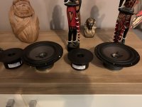
I recently picked up a bunch of those cheap JBL GX1200 drivers for $29 and started doing little projects with them and have scrap. I've wanted to play around with the idea of tactile response and impact with near field subs and also wanted to tinker with open baffle to learn from it and measure it and see what that's all about, satisfying a lot of curiosity for a few coins. I don't know how to model open baffle or free air driver response and behavior, so I just had to build it and see what it did.

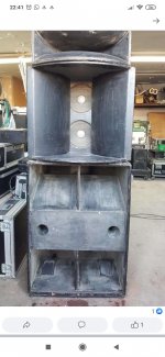
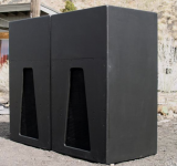
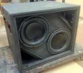
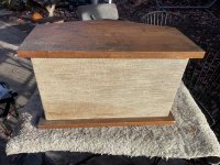
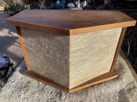
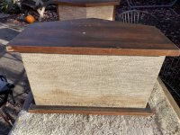
Keeping it simple, I started with a wedge that is about 22 degrees with a 30 inch tall back so that both the 12 inch drivers would fire into my chest and guts in my seating in my audio room. I ended up doing 30 inches (back) x 12 inches (base) x 0.63 inches (top) with a 31 inch face at a 22 degree slope. I gave it some braces between the drivers and in the bottom back. I wasn't sure how this would effect things but I know it needed at least some kind of bracing. All glue, no screws.

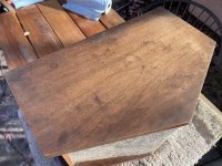
I rounded the edges and sanded it and then said, well, what the heck, and went ahead and pre-stain, stained (Early American) and then did a top coat of satin poly over this birch veneer ply scrap I have. I'm not going to see it behind a seat, but figured, if I do anything else with it it won't be bare timber.

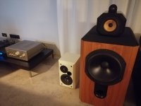
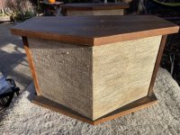
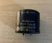
The drivers are ugly, the red JBL 1000w logo on the dust cap is hideous. I need to find a way to replace those inexpensively. They're $29 drivers so I cannot really complain.

I did some listening first, some music and a few movie scenes. Then I did some measurements, near field on the drivers and at the listening position with room influence. Pretty interesting results.

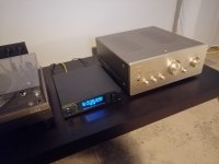
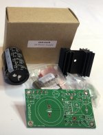
I wired them in series so they're around 8ohm. I am powering them with a 75 watt RMS at 8ohm Dayton sub plate amp in an outboard box of its own to keep it simple. No DSP. No EQ. At least not for testing at first. It has a built in 18hz high pass filter, and I just let it keep a low pass filter of 120hz or so. Later I tested it on my NX3000 channel to give it more output and was able to max it without ever seeing clipping or signal issues at the amp, so these 250w RMS drivers together can definitely soak up 500 watts no problem. They're both 12mm xmax so together they can move quite a lot.

Overall I like them for their effect for impact and tactile response. I did a crossover in my miniDSP to test them limiting them to 45hz~100hz basically with sharp drop offs so that they're basically mid-bass modules and then maxed the volume on them. It was interesting to have the impact in gunfire scenes in John Wick, Heat, Equilibrium, etc. Lots of thump in my chest from those with this behind the seat. It made me want to re-do this with 4 drivers to get even more.

For just general music listening it surprisingly sounds great. It takes a lot of amp to get them to be loud, but at around 35 watts per driver at 1 meter it was plenty loud for me for music and was capable of digging quite deep. Deeper than I expected. I would need a lot more amp to use them in a larger room and listen at greater distance for sure, but to off set that I would rather use more drivers. That's a future project.

20221118_142221.jpg


20221118_161451.jpg


20221118_165032.jpg


20221118_165037.jpg


20221119_104735.jpg


20221119_105820.jpg


20221119_154800.jpg


20221120_092212.jpg


20221120_091644.jpg


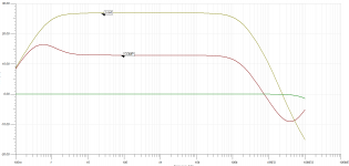
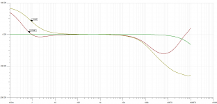
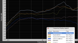
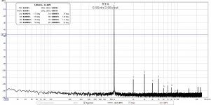
Here's some measurements. The top two are near field. The upper driver is in red. Really nice response from 30hz to 180hz. The drop at 34hz or so is due to the narrow wings at the top of the baffle. The bottom driver in blue. Same response, however, it has much longer wings next to its baffle and so I get the low end response from 30~34hz back. Learned a lot with just that simple bit on the sides with the baffle. For mid bass this didn't matter. For sub-bass it would matter a lot. When measuring these I referenced at 99db.

The green line is at the listening position with the room involved. Surpringly not bad, it kept bass pretty decent to 30hz. A little EQ and this could be flat. I referenced this at 90db. Ultimately this wasn't meant to do anything at 30hz or over 100hz. I just wanted to see what it would look like with the open baffle. This graph doesn't show it, but I later used a crossover in the miniDSP to set it to basically focus on 45hz to 100hz as a mid-bass slammer module.

NearField_ListenignPosition_Measurements.jpg


Fires into our guts and chest behind the seats.

It's really back heavy with those magnets. It actually leans on carpet. I think I will put some small feet in the back to keep it straight to counter the weight.

20221120_112229.jpg


Learned a bunch about open baffle with this. Will explore more. Also learned a lot about tactile response and impact. Going to focus more on this now.

Very best,

Harley setup

Hey folks. New here hoping the community can lend a hand.

I have a basic understanding of the audio system(s). I had just installed an audio system in my bike. Upgraded saddlebag lids, put in an amp, upgraded 6.5 fairing speakers and put in 8” hybrids and 2 tweeters in the bags.

I installed the system without the additional tweeters first, adjusted the gains and got a good sound. Then I installed the tweeters and ran them in parallel to the coaxial 8” hybrids. Doing that I got more power to the set but then I blew out one of the hybrids(started distorting and crackling intermittently).

I understand that parallel “halves” the impedance thus making more power available. However I should not be even close to the max handling of the speaker to blow it. I am certainly missing something

The amp is a 4-channel ds18 candy z4b pumping 100rms at 4 ohms and 150 into 2 ohms. Fairing speakers are 2ohms and adjusted nicely. Coaxials AND the tweeters are 4 ohms. Coaxials are rated 250 rms and tweeters 200 rms. There is a 2.8 k crossover installed on the positive lead between the hybrid and the tweeter.

What did I do wrong? Do I need to bring the gain down after installing the tweeter in parallel ?

To notch or not to notch

When measuring low levels of THD or THD+N the recommendation is often to use a notch and LNA.

Here is a measurement at -2dBFS of a AK4493 dac with ES9822PRO. Without notch.

ak4493d-L_ES9822PRO-L_1k@48k_-2dBFS.PNG


I get similar results with another ES9822PRO ADC so this is not device dependent. And just to show that this is not some heavy distortion cancellation here is the same setup but with at 2567Hz -3dBFS.

ak4493d-L_ES9822PRO-L_2k567@48k_-3dBFS.PNG


So very similar result.

Now let's use a -30dB notch + LNA (CosmosAPU). But before that here is a measurement without notch but at -32dBFS level.

ak4493d-L_ES9822PRO-L_1k@48k_-32dBFS.PNG


Third harmonic is now clearly dominating over 2nd. Hard to tell if this is due to DAC or ADC.

And finally a measurement at -2dBFS using Cosmos APU +6dB with compensation.

ak4493d-L_CosmosAPU-notch_ES9822PRO-L_1k@48k_-2dBFS.PNG


The harmonic profile is very similar to previous measurement at -32dBFS.

Now the question: compared to the first measurement without notch why would this notch measurement be considered more accurate?

SMPS powered JLH 69 - quick and dirty results

I just wanted to share some things I found today while playing around. I recently bought a connexelectronics 48V SMPS500R-single to power a Pass Zen v1 amp that I have. Unfortunately when i tried the SMPS on the amp my outputs shorted internally(I am still not sure what happened) so no more Zen V1 until I figgure out the issue.

Today I decided to try my SMPS on a JLH 69 amplifier I assembled using MJ15003 outputs and an unregulated linear supply. With the linear supply the amp sounded good but it never sounded like something special. It was easily bested by my Decware Zen select when A/Bed on multiple occasions. It also always had a slight hum on my parker audio 98s (96db/watt/m) but you couldn't hear it from the listening position.

With the SMPS I had no hum and no noise from the speakers and it sounded better in every way. The soundstage was bigger, the sound was clearer (less veiled) and the bass was improved. The amp now sounds like a real high end amp to me. I have not A/Bed it with the Decware Zen select but if I were to make a guess I would bet they are now close to the same level but just different "flavors". I think I may order another smps with the proper voltage for my JLH and make this a permanent addition.

BTW i tried adding a 1mh coil between the smps and the JLH to clean up any noise from the smps. I previously tested this unloaded and the coil did lower the noise output on the smps. I found however that this had a negative impact on the sound of the amp. The bass seemed to be reduced and it gave the amp an overly forward sound. If I were to play with this again it would be with an inductor made of a much higher gauge wire. Honestly I really don't think it is needed.

I put this up so that any of you who still think SMPS is not for hifi. I think the technology is here and could be used to push some current amplifier designs even further. If you haven't played around with SMPS I suggest you give it a try.

Learning by dissecting circuits

Hello,

My usual warning: I am learning. I have much to learn. I will often ask stupid questions and reach incorrect conclusions. Thank you for any education you may give me.

I am trying to learn more about tube amplifier circuits by reading and dissecting examples.

Case in point:

circuit.jpeg


I already peppered this one with questions (A, B, C).

I also assume that only capacitors at 1 and 2 would affect frequency response. Am I correct?

I still have much to learn about picking proper operating points for the tubes themselves. I am not sure if the values shown on this drawing are anywhere near correct. But I suspect they may be odd or wrong. (but it's probably just me and my ignorance)
But in that regards, how can this design be compatible with all of 12AT7, 12AX7 and 12AU7?

Finally, do you know of any reference that would inventory circuit patterns found in tube amplifier designs? I have not been doing this for very long, but I think there are quite a few pieces that appear in many designs and it would be O so wonderful if they were catalogued and explained somewhere.

Again, thank you for any help and sorry for the stupid questions.
  • Like
Reactions: vdljev

Small sub

Hi everyone,

I recently looked at the small powered sub from Fostex that uses a 200mm driver and was wondering if there were any designs using even smaller drivers?

I know the (sorry to use the 'B' word) Bose Acoustimass literature says it uses 3 smallish 5.25" drivers in a seventh-order band-pass config (3 chambers + x-over?)

Are there any known designs that use a 4 or 5 inch driver(s) in a small cabinet to give sub-woofery-type noises?

I have access to a CNC router, so cutting fiddly bits isn't an issue.

For all I know, small drivers and subwoofer may be competely incompatible,

but I thought I would ask.

Any help will be appreciated.

Sidegig Guitar EVM from Texas Instruments thoughts?

Not sure if this is the right place to post but has anyone actually tried the SIDEGIG-GUITAREVM from Texas Instruments?

Here is the evaluation board
http://www.ti.com/tool/SIDEGIG-GUITAREVM

And it plugs into the TPA3255 Class-D amlifer
http://www.ti.com/tool/tpa3255evm

I am wanting to build a Bass amplifier and want to base my whole design around the TPA3255 amp and use the SIDEGIG design as my preamp and overdrive circuit but I am worried it might not sound as good as I want it to.

Has anyone tried it out yet?
If I posted in the wrong section please let me know where I should post...

ATI Amplifier Schematic

If anyone's ever been curious what ATI is putting into their amplifiers, here is a schematic I found. Generally speaking, their schematics do not seem to have been published. For those who aren't familiar with ATI, ATI is a fairly large US-based amplifier manufacturer that has not outsourced everything to China. They have OEMed products for a number of companies, although for the most part they don't admit whose products they make. Their calling card, though, is individual amplifier modules and you can usually tell their products from the back panel.

To be fair, this schematic is actually for the Earthquake Cinenova Grande circa 2014. They were kind enough to post it on their European website (by accident?). The amp is clearly an ATI. The original versions had the same goofy parallel port connector ATI introduced (and which went nowhere), the modules use the same heatsink as the ATI AT2505, the topology is a complementary diff which ATI is known to use, and so forth. Whether ATI still uses this exact circuit in their house branded products, I don't know. I suspect in lower priced OEM gear like the Monoprice Monolith they do (less a few output devices). Their new high end stuff is a fully balanced design, so is different.

This is a fairly simple design complementary differential input design, without a whole lot of tricks up its sleeve. It is what it is and perhaps someone will find it useful if they're trying to fix one. Or are curious how a particular design performs. (Bench tests at Product Review). I suppose they had to keep the parts count down to fit it all on the module? Who knows. There is a lot that could have been done here that was not. My guess is that this is close to the same thing (or even less sophisticated) than what Jim Bongiorno designed for SAE more than 40 years ago (which was owned by the same people as ATI).

Attachments

  • ATI-Earthquake Schematic.png
    ATI-Earthquake Schematic.png
    117.1 KB · Views: 1,363

Getting 60W from 6C33C push-pull

Hi guys, is it possible to get 60W of power output from a pair of 6C33C? I see some designs getting 40W out from pushpull Class A. How about Class AB 6C33C with more of power output? Can anyone recommend bias point?

I'm also looking at EL509 triode mode which has Rp of 200 ohm. It may be a good alternative to 6C33C class AB because of its high peak current?

Thanks in advance for your suggestion. 🙂

TPA3255 repeated fault when cold

Hi all,

I custom built an 8 channel amplifier made from 4 separate TPA3255 dual channel amplifiers with a microcontroller coordinating their reset based on time and the input voltage levels. They all exhibit the same issue.

The issue is, when I first turn the amplifier on and it's at room temperature, the TPA3255 will be brought out of reset after the the microcontroller has seen the power supplies have settled (12V and PVDD) then the microcontroller will connect the speakers through the output relay. Now, everything will be fine for approximately 3-5 seconds when the TPA will go into fault mode (FAULT -> 0 and CLIP_OTW -> 1). The microcontroller then disconnects the amplifier by turning off the relays, puts the TPA3255 into reset, waits 1s, brings the TPA3255 out of reset then connects the speakers via the relay once again. Now the cycle repeats for about 10mins until the heatsinks are a little warm to the touch.

Could anyone suggest why the TPA3255s might be behaving this way? Attached is my schematic.

Many thanks,
Boscoe

Attachments

Pair Scanspeak tweeter and Royd midbass

For sale pair of tweeter and midbass,used but good condition,taken out from Royd audio Apex speakers.Price for all 4 units 60 euro plus 15-20eu shipping inside europe.If interest plese contact me.Paying thru paypal.

Attachments

  • E6DED1ED-0B53-4570-8E34-7472552FB247.jpg
    E6DED1ED-0B53-4570-8E34-7472552FB247.jpg
    983.9 KB · Views: 229
  • 17AAF48B-5689-4755-9268-30A81F5F72CA.jpg
    17AAF48B-5689-4755-9268-30A81F5F72CA.jpg
    977.7 KB · Views: 209

Why not Cirrus or TI or something other than ESS and AKM?

There’s the ESS hump
then AKM is trying to get back on its feet and is considered soft sounding.…..


why don’t DAC manufacturers use other chipsets like Cirrus or TI or something else?

i don’t get it.


out of a bunch of DACs I tried. The Topping D30pro which uses the newest Cirrus chip sounded most natural. Lacked weight and punch, but I think that was just toppings fault at a sh$$ty implementation.


so why all the fuss around ESS and AKM when nothing new in DACs which use these sounds so good?


cheers

Remote control kits

As some people here may know, I have designed some remote control boards.

So far I have a small board for controlling a motorized pot, and two different boards for "passive preamps". A lot more will be added, when I have to time to get it finished 😉

You can read about them here: http://electronics.dantimax.dk/

And you can read some of the background info on my personal website.

Best regards,

Mikkel C. Simonsen

LF driver help

I have a FR 8" Diatone alnico driver in a 1cu ft enclosure which is ported. I like it, but bass is lacking. I was thinking of installing a 8" woofer to the rear of the cabinet and running it so I get a push-pull effect. I would have to attach it to the outside on the back, and face it towards the front speaker ( not enough depth to put it inside). Anyone ever try this? Diatone is 4 ohm...so how to connect...in series?

Why are there almost no JBL 2235H equivalents?

JBL 2235H.

The only equivalent (possibly superior) driver I have come across is the AE TD15H.

This driver seems to be super versatile. High sensitivity, low Fs. Good for subwoofer, two way (crossed over to a CD-Waveguide), three way, Hi-Fi, HT, SET amps... what have you...

I wonder why nobody is making such a driver now, other than Acoustic Elegance. Or am I missing something?

For Sale 2015 Sony VFETs part 2 FE pcbs

Hello,

I have for sale 2 stereo pcbs done after the article in the title.

https://www.firstwatt.com/pdf/art_sony_vfet_pt2.pdf
Schematic on page 5, only what regards the front end.

I used them as a balanced preamp with very good performance.

I attached a photo of the part that is included on the pcbs.

The pcbs come with all the parts populated except the active parts in the signal path(jfets, bipolars, mosfets).

I have also the low noise power supplies that I used with them.

Sold


EDIT: attached also a thd measurement done with the same power supplies I sell here and the semis I removed.

Attachments

  • 0699EDF8-1CB7-4A04-B03E-83B114F21CF3.jpeg
    0699EDF8-1CB7-4A04-B03E-83B114F21CF3.jpeg
    189.1 KB · Views: 398
  • 449C7EC7-3DE2-4C7B-9D63-9D7BAFF52274.jpeg
    449C7EC7-3DE2-4C7B-9D63-9D7BAFF52274.jpeg
    390.4 KB · Views: 407
  • D137CD39-1701-458D-802B-965D1E096DE5.jpeg
    D137CD39-1701-458D-802B-965D1E096DE5.jpeg
    377.3 KB · Views: 381
  • 0.56vin 3.66vout.jpg
    0.56vin 3.66vout.jpg
    120.2 KB · Views: 348
  • C2AA3251-0438-4CFB-A213-CD33BEB3606B.jpeg
    C2AA3251-0438-4CFB-A213-CD33BEB3606B.jpeg
    444.3 KB · Views: 52

FS new Lundahl Chokes , 2x LL1673 200mA/10Hy, 2x LL2742 90mA/46Hy

FS:

hi all, selling for a friend:

2x new choke LL1673, 200mA/10Hy - both 200€ shipping included in EU​

2x new choke LL2742, 90mA/46Hy - both 200€ shipping included in EU​

unused and never mounted, parts got from Jacmusic.com

Attachments

  • IMG-1535.JPG
    IMG-1535.JPG
    517.7 KB · Views: 83
  • IMG-1536.JPG
    IMG-1536.JPG
    413.3 KB · Views: 79
  • IMG-1537.JPG
    IMG-1537.JPG
    486.7 KB · Views: 73
  • IMG-1532.JPG
    IMG-1532.JPG
    379.5 KB · Views: 77
  • IMG-1533.JPG
    IMG-1533.JPG
    496.2 KB · Views: 76
  • IMG-1534.JPG
    IMG-1534.JPG
    516.8 KB · Views: 78

ADAGIO from Dr. Bora Jagodics

New year, new build,in progress, tone correction preamplifier with 12AX7EH schematic ADAGIO from Dr.Bora Jagodics (R.I.P.) . Second build this year .....
Regards,
Alex

Attachments

  • IMG_20190205_184135-001.jpg
    IMG_20190205_184135-001.jpg
    983.6 KB · Views: 1,216
  • IMG_20190205_184147-001.jpg
    IMG_20190205_184147-001.jpg
    864.4 KB · Views: 1,103
  • IMG_20190205_184214-001.jpg
    IMG_20190205_184214-001.jpg
    927.7 KB · Views: 936
  • IMG_20190205_184223-001.jpg
    IMG_20190205_184223-001.jpg
    844.5 KB · Views: 906
  • IMG_20190205_184235-001.jpg
    IMG_20190205_184235-001.jpg
    982.6 KB · Views: 830
  • IMG_20190205_184254-001.jpg
    IMG_20190205_184254-001.jpg
    981.9 KB · Views: 324
  • IMG_20190205_184302-001.jpg
    IMG_20190205_184302-001.jpg
    984.4 KB · Views: 350
  • IMG_20190205_184311-001.jpg
    IMG_20190205_184311-001.jpg
    1,000.3 KB · Views: 399
  • ADAGIO SCHEMATIC.jpg
    ADAGIO SCHEMATIC.jpg
    162.1 KB · Views: 779
  • Like
Reactions: Machina

For Sale Bose 901 (pair), with stands, No EQ box

For sale is a pair of used Bose 901 speakers, untested and sold as is. I acquired these as a project that I longer have time for. The veneer is rough but not unrehabilitable. One loudspeaker is in tougher shape than the other. You can find these for sale, often missing either the EQ box or stands. This pair has the stands but no EQ box, which is less an issue as modern DSP has made the issue mute. I haven’t checked on the drivers but I’m sure the original foam surrounds requires that some of them be replaced; in this instance, one would replace them all regardless. See pictures.

Local pickup only, Oakland (Bay Area, CA). $30

Attachments

  • EEABF522-7591-408A-AF5E-F6C079940AD5.jpeg
    EEABF522-7591-408A-AF5E-F6C079940AD5.jpeg
    869.6 KB · Views: 149
  • A0999172-0485-4A58-93AD-DE3D800887F0.jpeg
    A0999172-0485-4A58-93AD-DE3D800887F0.jpeg
    821 KB · Views: 122
  • BBACACEA-3D97-4D8F-A62B-1CFC7E988405.jpeg
    BBACACEA-3D97-4D8F-A62B-1CFC7E988405.jpeg
    781.6 KB · Views: 122
  • A1786006-AB69-446A-9C75-5F606BDFBDC9.jpeg
    A1786006-AB69-446A-9C75-5F606BDFBDC9.jpeg
    837.2 KB · Views: 124
  • FB254FE4-BEDD-4F8A-A1CE-67DC0D479028.jpeg
    FB254FE4-BEDD-4F8A-A1CE-67DC0D479028.jpeg
    848.2 KB · Views: 162
  • 3FDA04C5-B676-4A8B-AAAE-D62C81CDEDBF.jpeg
    3FDA04C5-B676-4A8B-AAAE-D62C81CDEDBF.jpeg
    737.2 KB · Views: 135
  • 56015CC3-9AB6-46D2-8DB4-8AB7217671D1.jpeg
    56015CC3-9AB6-46D2-8DB4-8AB7217671D1.jpeg
    808.5 KB · Views: 157

Filament voltage and tube hum

I am working on a Magnecord 1048 Tube Reel to Reel. It has a tube preamp stage which include a 7025 and a 12AT7. The issue is that no sound coming out of 12AT7 pin 3 (the output). If I manually feed audio to the input of 12AT7 (Pin 7), it is all good. But if I feed audio to the input of 7025 (pin 7), then I get nothing even if I turn the volume to the max.

After some test, I noticed that the Filament voltage of the 7025 (between Pin 4 and pin 5) is only around 4v. So I adjusted the variable resistor to increase the 7025 filament voltage to around 6v. Now, there is hum coming out of the 12AT7 output and it is increaseing/decreasing with the turning of volume control. So I think the 7025 still has some issue. Any suggestions?

2.jpg


1.JPG

6550 SED "Winged C" matched set 16 tubes

SOLD


Selling quads. One set remaining
$375 plus shipping

NOS Never used other than testing and burn in by vendor. I bought 5 years ago and sold my amps.
If you are looking you know these are rare and some say the best 6550 tubes ever made and will never be made again in all likelihood. They are Russian Svetlana not those TAD or any relabeled newer production.
Most are dated around 0144 so later 2001

Attachments

  • 6D0A5D68-A1FD-4471-9D75-454149801435.jpeg
    6D0A5D68-A1FD-4471-9D75-454149801435.jpeg
    158.1 KB · Views: 145
  • EFA376B4-5B1F-4FA5-B190-0569E1A97C3F.jpeg
    EFA376B4-5B1F-4FA5-B190-0569E1A97C3F.jpeg
    275.7 KB · Views: 151
  • A3A19734-3191-4947-8D3E-89B796A27D49.jpeg
    A3A19734-3191-4947-8D3E-89B796A27D49.jpeg
    462.1 KB · Views: 159
  • 0DB4669F-2710-4392-B5B7-A3177FE72CA6.jpeg
    0DB4669F-2710-4392-B5B7-A3177FE72CA6.jpeg
    384.1 KB · Views: 133
  • 688EBCD3-FC65-461A-9C1F-FF379036A9FC.jpeg
    688EBCD3-FC65-461A-9C1F-FF379036A9FC.jpeg
    301.3 KB · Views: 152

Anyone tryed cleaning records with wood glue?

Sounds just like a thing not to do, but internet is full of people that had done that, with evidence and it sure does remove alot of noise.

On the other hand internet is full of people suggesting not to use anything other than records cleaner or some cleaning kits.

I have some old 7" records that I'm willing to use for testing and if I will get good results repeatedly I'm willing to use it on some records that I had bought recently. I believe that there are particles of paper degrading... Albums smell like mold. There is alot of surface noise, but visualy records look ok, soap and distiled water helped a bit, but not much.

Before trying I want to hear your opinions?

FOR SALE or TRADE: Black Gate VK 22µF 350V caps - will trade for tubes

I have 4 unused Rubycon Black Gate NK capacitors (22µF 350V) and one used 150.µF 350V.

These are now unobtainium.

Brand new, never used. They were bought from PartsConnexion in 2005 for a project that was eventually abandoned. I'd forgotten I even had them until I moved and had to clean up my "projects" bins.

I rate them as a 10/10 (Mint) as they are technically NOS (the four 22µF 350V).

$300 for all five caps or will trade a pair of tubes. I'm looking for:

  • Sophia Electric EL34 ST
  • Blackburn Mullard EL34
  • Genalex Golden Lion KT77

Attachments

  • IMG_1250.jpg
    IMG_1250.jpg
    528.9 KB · Views: 87
  • IMG_1259.jpg
    IMG_1259.jpg
    500.1 KB · Views: 42

Dynaudio Esotec D-260 replacement diaphragm

Has anyone successfully used the diaphragms available on Ebay from China to replace faulty units on the D-260?
https://www.ebay.com.au/itm/155073132755?hash=item241b1438d3

While the Ebay item does have a 28mm, 8 Ohm voice coil there are some slight differences to the original diaphragm. Firstly, the Ebay item is only 42mm overall diameter compared to the original at 45mm. On the D-260 diaphragm terminal plate there is a raised plenum area with a diameter of exactly 45mm so it is easy to ensure a genuine diaphragm is correctly centred. With the Ebay item you would need to accurately inscribe a circle onto the plenum surface to match the outer diameter of the new 42mm diaphragm. Get the centre point a fraction of a mm off centre and the voice coil will scrape down the side of the magnetic gap.

On the original diaphragm the lead wires from the voice coil are brought out to the front side of the diaphragm but on the Ebay item they are left on the underside. This means that small holes must be made adjacent to the voice coil so that the lead wires can be poked through the diaphragm to get to the top side.

Now if one can overcome these problems it should be possible to fit replacement diaphragms from Ebay to the venerated Esotec D-260 and restore them to near new performance.

I welcome any input and advice from those who may have tried this operation.

Dilema on what route to take double 18s reflex or TH

Guys,
i wanna share a story and ask for some advice
last friday i did a gig on a small bar around 100 people max ( tecno cumbia band . aka selena quintanilla , elida reyna )
i own 4 LX18's (b52) that i did not used that gig cause i did not had help to move the boxes

anyway a friend have their kids ( on their mid 20's ) who help him with his speakers
so he offered to put the set the speakers for me,

i played that place before with the LX18's (i have 4 but used just 2 ) and 2 tops ( jbl MR925's)
i drive the 2 LX18's with a bridged crown XLS2500 and the jbls with a bridged XLS2000
with an old drive rack PA

so this was the thing, he lent me and move for me 2 yamahas CW218V's (dual 18 bass reflex ) and one carvin TRX215 as top
i adjusted the LP filter to 24db LR 30 HZ for the yammies and HP to 24db LR 100HZ
the yammies are rated at 30hz freq response and i can go lower on the LP setting but i wanted to play safe as those was not my speakers
( i tweaked the attenuation knobs on the amps so to have a balanced subs to tops balanced )
as i never played with that speaker setup before

anyway, after putting some reference tracks on the sound check i EQ'd the master bus on the board ( behringer X18 ) some BELL -6db on the 125 HZ range with a Q of 1
that taked off the boomines of the system/room sound and let the subs sound more punchy , i also attenuated BELL around 3-4k with -4db with a Q of 1 to take away the
harshines of the carvin top and boosted around 10k high shelf +4db
that made the tops to play more to my taste

ok so, the system was playing around 30-40 percent on the power amps lights
and i was impressed with the sub info coming out from the yammies, it felt more visceral, ( subs was next to me around 2 feet )
but people on the dance floor were more ecstatic if you can call it, as i can tell how they were dancing and compare to other times, indeed the smile on my face for how the sound was performing cant deny how i was enjoying the gig.

The workers and managers at the bars told me, hey we never heard that much bass coming from any system here ( i mean other bands own PA ) and not even my system
in fact the other guys do not have a sound guy and locally the knowledge in audio from local bands are close to none, there is a guy who plays with 4 QSC KS118's and 2 KLA12's
and not even sound half as good as the yammie system. ( told by one of the bartenders who also plays in other bands )

anyway, my point is that i was able to squezze the most i can get from the system even i was not playing to their limits but i mean that not with my own speakers i liked how it sound.

So do i switch to dual18's bass reflex that are easier to build as DIY or do i try the keystone or TH18 ( i know those cant compare to my rubish LX18's that i know not even were good designed like CV L36 )

If i go to double 18's what designs you recommend ( 18sound and b&c have recommended plans on their website also )
is there any bandpass design you guys recommend
and from from the horns and tapped horns what you guys recommend

I was truly impressed how i can feel the bass with 2 double 18's cabinets and i knows those yammies are not the best design

i want to start with 2 cabinets, 4 being ideal but will scale to 8 in the future

I just love the compliments if people that says that the band sound awesome and other that says
" your system rocks"
"never heard a system like it"
"this thing punch you in the chest"
" this make me to dance"

Phun intended !

thanks for making DIY one of the best places for advice and help
you guys ROCK!!!
Best.
Max.

Question on QUAD 303 current limitations

Has anyone tested, or have an idea, of the output current bottleneck in the 303?
The usual suspects are:
1- transformer voltage collapse
2- power supply regulator circuit collapse/limiter
3- amp output stage (or drive) limiter.

I figure the recommended 67V supply voltage is a function of how much the pre-regulator 80V collapses under high current demand.
So may be a higher capacity transformer would also allow a little higher regulator voltagee.

I would like my 303 to breathe better with my sub-6Ohms low-impedance speakers.

Boxing in transformers?

Hello, starting my first build with OPTs today, along with a power transformer I wound myself just yesterday but as all of the transformers are unshielded and I have some mumetal around I was wondering if it would be worth the time to construct some boxes around them to keep any interference away?

Maybe just wasted time and definitely something I could add later but thought I'd ask 🙂
  • Like
Reactions: Ixnay

Digital IIR Inverse RIAA filter 1kHz @ 0 dB Audacity Nyquist

Any Nyquist mathematicians out there able to help me out in creating an inverse RIAA IIR command that can be plugged into Audacity's Nyquist prompt? The sampling frequency is 96 kHz, and it needs to have 1 kHz with 0 dB gain.

I've been playing around with the Wayne Stegall program, but either it doesn't work the way I think it should or I've critically misinterpreted something. I'm pretty sure that the program is misleading at first glance to newbies like me because the "zero frequency" is actually a pole around 50 kHz and not where you tell it that that frequency should have zero gain (?). I've tried a bunch of things only to get errors or very mangled/destroyed waveforms. I know a pretty good deal about a lot of 78 RPM restoration but not so much about Nyquist. Hopefully this is possible. Thanks!

Now that I think about it, maybe it would work if I told it to implement a gain of around -20 dB? I want to be sure to make as few gain changes as possible and have it be the exact same thing as if i transferred the record with no RIAA emphasis/deemphasis in the first place. Expert opinions needed.

http://waynestegall.com/audio/riaaiir.htm

Beginner REW / Volumio advice please

I think I might be being a little dim here.
Or i have missed an obvious point.

I think that maybe I have confused myself reading bits and bobs.
I think this might be more of a Volumio question.

I have been dabbling with my source and PSUs.

I am using a USBridge Sig and Volumio.
Just bodged together a 'Fast, fun inexpensive OB project'.
Pretty pleased.

My next thought wandered to my room and picked up a Umik-1 and downloaded REW to my laptop.

I have loads of questions, but am kind of stuck on step 1.
'Connect to your system'.

I can play an audible sweep by just plumbing the 3.5mm output of the laptop through my amp.
I can record and see the graphs produced and am looking forward to learning what it shows.

Am I right in thinking that this is good enough for room treatment?
I am not looking to do anything major, I am just curious to see if I have any major issues.

However, am I right in thinking that i can use this now to listen to my speaker output and/or my system output to see where I am at?
In which case, I am thinking that i need to put digital signal into the USBridge sig so it gets the whole system, using the DACs and PSUs etc.
In other words, I am thinking that i want to make my laptop and REW a digital source for Volumio?
Probably via USB?

I generally stream over the internet or access a separate source via LAN or use a USB stick as a source.
But I can't find how to use a laptop (or, out of interest, a phone?) as a USB source.
I have tried fiddling with Volumio, but I haven't done the right thing yet.

Am I thinking right or have I got this wrong?

After the above, my next bit is that I can't access all of the settings like any walkthroughs show, but am wondering if they might show after i manage to connect properly.
Currently, step 3 is 'set output on laptop to 48kHz' I am using a Linux OS on it and it doesn't seem to have that option that I can find.

Thanks.

DIY Soundsystem Build Suggestions

I am looking to build out a complete soundsystem. Right now I built 2 tapped horns as subs and plan to build a second pair. They run from 27Hz to 200Hz but would like to crossover around 150Hz or so.

I am going for the "wall of speakers" aesthetic and am hoping for some suggestions on what to build for the midbass/tops. Here are the current constraints: Total sub depth is 30" but they have angles corners, depth at the top is roughly 25.75". A pair of the subs side by side, rubber feet to rubber feet is 46.5" wide. The subs are 45" tall. The pair of the subs will hit 130dB on the lower passbad continuously, 135/140 dB on the upper passbad. It is also worth mentioning that the pair of subwoofers have a rough maximum continuous power of 1000W per pair. It would be nice if the midbass bins to have a similar power rating.

What I kinda had in mind was to have some sort of W-bin type enclosure for the midbass and have a constant directivity horn with a horn driver crossed over at roughly 400Hz from the midbass horn. That is just a rough idea and I'm not sure if a W-bin would be the right type of enclosure.

Any suggestions/thoughts? In order of priority the characteristics of the system go: Efficiency/Sensitivity, Aesthetics, Fidelity, Size (somewhat portable). Rough budget would be 3-4k USD.

Has anyone bought TO-3 transistors lately?

I see the MJ15003/4 are back in stock at Digi-Key, albeit at ridiculous prices ($10). These were once my favorite audio transistors, and they are still capable of excellent audio today. The MJ15024/5 are slightly less expensive ($8), probably because they have slightly lower current ratings.

However, I don't see TO-3 transistors in any equipment from the past two decades. I expect that old designs are the only things keeping these transistors in production.

Given the comments about fakes, would you trust TO-3 transistors today?
Ed
  • Like
Reactions: Ite

Marantz TT42 tracking force...

Hy,
I own the mentioned TT and people online are stating that you cannot upgrade the cartridge because the tonearm had fixed tracking force...

Now this might sound as a complete nonsence as I'm new to TTs,
but there is a screw at the base of the tonearm that clearly changes the tilt of the tonearm.
I had to adjust that screw when I received the TT, because tonearm was clearly too low. It will adjust the tilt for about 1cm end to end.

Isn't tracking force dependable on the tilt?
I understand that there is no VTA adjustment and that the tilt should be in parallel with the record.

Even if this is not the solution why couldn't I remove / cut the counterweight of the tonearm and install adjustable one?
Am I missing something?
Projects by fanatics, for fanatics
Get answers and advice for everyone wanting to learn the art of audio.
Join the Community
507,483
Members
7,873,699
Messages

Filter

Forum Statistics

Threads
405,557
Messages
7,873,699
Members
507,483
Latest member
kuttisrank