JL Audio Slash 500/1 low ohm led

Hello, I have a 500.1 rev 11 amplifier, which arrived with a damaged output stage and the mic4427, 1 240 ohm resistor, 1 75 ohm resistor and the 4 irf540 fets were replaced, but now the low ohm led turns on and I notice that it is not I have power on the mic, I only see 1.3v, any advice to know why the yellow led was understood. Regards

Attachments

  • 20230105_132152.jpg
    20230105_132152.jpg
    570.7 KB · Views: 223

Sonodyne SM100AK MOD

Hello everybody,

I have these, SM100AK speakers, bought quite a few years ago. They are nice, but I think there are things to improve.
So from time to time, I make some mods, so to make them sound as much as they can. Worth it or not, to put money in these, not sure, but it is like a sport
and it is kind of interesting how things can evolve and improve 🙂

So what was done. I have changed all electrolytic caps to Panasonic FC and Panasonic NHG 4800uF in the power supply. There are some left few Chinese bipolars and
I'm thinking to change them to 'Muse'..? The film caps are Polyphenylene Sulfide, I don't why I changed not to Polypropylene, but it was done a long time ago. Is there much difference between Polyprops and these? Would you increase the size of the power caps? Bypass them with film caps? What would do to improve it?

I have shorted the Volume pots, and improved the sound a lot. The box is made of aluminum, so it has a very nice metallic sound 🙂 I have put bitumen adhesive material inside the walls and that was an improvement as well.

I'm wondering to change the ICs now. It has 3 x TL074 and 1 x NE554. 3 x opa1644 + 1 x opa1612? What do You think?

Any ideas are very welcome on how to improve it even more?


Thanks and have a good day.

Attachments

  • IMG_0859.jpg
    IMG_0859.jpg
    396.8 KB · Views: 191
  • IMG_0864.jpg
    IMG_0864.jpg
    523.3 KB · Views: 188

How to enable qobuz on Daphile

Good evening,

I'm a newbie Daphile user and I'm not able to set qobuz on it.
My Daphile version, that is installed on an Intel NUC PC, is the daphile-21.01-x86_64. The installation is on NUC hard disk and works fine for example with Tidal.
My problem is that I don't know where and how I can insert qobuz credentials.
I see the Qubuz plugin in Advanced Media Server Setting under "Third party plugin" (see picture) but not in the "Active plugins".
I tried to install the Qobuz app on my Squeezebox, but there isn't a Qobuz app (only Tidal one)

Could you please give me suggestions?

Many thanks to any people that will answer and sorry for my bad english!

Bye bye
Andrea


1648318728916.png

Hornresp compression and velocity

Hi there, I've been messing around with hornresp and simulating a tangband w5-2143 horn. I'm aware that the compression ratio shouldn't normally exceed 2:1 for high Xmax drivers, and port velocity shouldn't ideally exceed 14 m/sec. But given this is a 5" full range driver with a Xmax of 2.5mm, how high can my compression ratio go?, Is the limiting factor throat velocity?, can I simulate total harmonic distortion?. Currently it's compression ratio is 8.90:1 but it's throat velocity is only 14.5 m/s (at 30 watts). I know that at 30 m/s a port hole on a reflex box will begin to seal over and not function, but my question is will my horn destroy the driver or will it sound horrific?. The reason why I have even bothered to ask is because I saw plans for a XKI cabinet for the w5-2143 here: https://www.diyaudio.com/community/threads/xki-xs-ab-initio-karlson-6th-order-bandpass.268524/

And I would guess that it also has a high compression ratio.

The Perfect Speaker System for YOU?

I've always wondered tape packs from raves are so much more valuable than other recordings. The majority this forum believe they seek 'perfection' - a flat frequency response.

Bygones.

Perhaps those who got out during their youth are looking to re-experience their youth. Bose and other big-box manufacturers this. Flat? Flat is crap - nobody's hearing is flat.

Sound is subjective. It's DIYAUDIO - the object of the exercise is to reproduce 'the sound you like'. As the man says," It was the best of times . . ."
If you're of a certain age . . . your first experience of musical joy was "Good Times" being pumped out of 2 x 12" disco speakers in a woefully undersized cabinet with screechy scratchy Piezo tweeters providing the treble. The DJ is maxing-out his 120w amplifier.
You grew up, you got a car. The first thing you did was to buy a graphic equalizer to make the music LOUD. The very next thing you did was to set the frequencies into a 'smiley face' - big-up the bass, big-up the treble!

You never wanted flat.

System Clock Oscillator .... does it reduce THD?

Working on different DSPs, with ADCs and DACs, I was wondering what happened to the ultimate clock.
Remember 10 - 15 years ago, every body wanted to change the clock in digital sources like CDs to something fancy from better discrete Xtal oscillators, over TCXOs to OCSOs.

Have anyone done some THD test of such changes?

I'm planning on using X1E0000210427 https://jlcpcb.com/partdetail/SeikoEpson-X1E0000210427/C841675 which is a 10ppm Xtal, in conjunction with a ADAU1452

But I could go for a Crystek CCHD-575 https://www.audiophonics.fr/en/comp...p-12445.html?search_query=osci&fast_search=fs
Promising very low phase noise.

Or one could go crazy with a real OCSO https://www.golledge.com/products/sine-output-oven-controlled-oscillator-with-5v-supply/c-26/p-285

Or a NeutronStar!?!
http://www.newclassd.com/index.php?page=36


The big question is whether it has any impact at all on performance, or it is just an impact on the wallet 😉 .....

RK27 Breakout pcb (try out)

Hei folks, iam noob in electrical engineering, to muffle my boredom i try to make schematic and layout for rk27 breakout pcb. So is there any wrongdoing about my drawing?

Attachments

  • rk27 layout.png
    rk27 layout.png
    18 KB · Views: 126
  • rk 27 sch.png
    rk 27 sch.png
    5.5 KB · Views: 114
  • rk27 layout.pdf
    rk27 layout.pdf
    41.7 KB · Views: 70
  • 3d bottom rk27 layout.png
    3d bottom rk27 layout.png
    21.1 KB · Views: 106
  • 3d top rk27 layout.png
    3d top rk27 layout.png
    16.4 KB · Views: 117
  • top rk27 layout.png
    top rk27 layout.png
    6 KB · Views: 106
  • bottom rk27 layout.png
    bottom rk27 layout.png
    7.7 KB · Views: 105

Nakamichi DVD-10s

I have Nak DVD-10s that I have owned since new. I dusted it off last year after finding an AV-10 and getting that working, and both now power the various vintage speakers that I repair from time to time in my garage.

I only use it for CD’s and noticed that it won’t read a disc for about 5 minutes before turning on. Initially i thought it could have been due to condensation on the laser or similar, but it’s still happening in the middle of summer.

Just wondering if anyone has any suggestions on what to look for. I heard these have failed lasers often, but this one works very reliably once it has warmed up.

RTP Streaming to Raspberry Pi with CamillaDSP from a desktop computer

Hello all,
I just finished my setup where I can digitally stream my audio from the desktop PC to a CamillaDSP server connected to the speakers. This took me two days to get running properly, so I wanted to post here a breakdown of it. Hopefully it will help some of you.

  • Desktop PC as source
    • Ubuntu with Pulseaudio
    • Pulseaudio resamples all to 96kHz with speex-float-5
      • PA uses 0.3% CPU still after this, on a Ryzen 5700g
    • PA transmits to network using rtp module (Only 16 bit integer was possible.)
      • load-module module-null-sink sink_name=rtp_2_camilla channels=2 format=S16BE rate=96000 sink_properties="device.description='RTP to CamillaDSP'" load-module module-rtp-send source=rtp_2_camilla.monitor destination_ip=192.168.0.22 port=46908
    • Running pulseaudio with -vvvv, I find all the RTP settings as SDP data. I put these in attached sdp file.
  • Raspberry Pi with Raspbian OS 64 - Server for DSP
    • Uninstalled Pulseaudio, only using Alsa
    • Installed ffmpeg, camilladsp, all other dependencies
    • Running attached Python script to check for incoming streams
      • Pings my desktop PC to see if it is on. It shuts down the amplifier if there is no ping response.
      • If my desktop PC pings back, script will turn on the amplifier and run ffmpeg to check for RTP stream.
        • Uses the sdp file to recognize the incoming stream
    • ffmpeg outputs the stream to snd-aloop loopback device at hw:0
      • This creates a virtual device for Alsa and makes it possible to capture audio from an application, in my case ffmpeg.
      • Channel count needed to be corrected for snd-aloop, to match the RTP that has 2 channels. By default it has 8 channels.
        • $ cat /etc/modprobe.d/sound.conf alias alsa-loopback snd-aloop options snd-aloop pcm_substreams=2,2 index=0,0 enabled=1,1
      • It is tricky to minimize delay of this RTP stream but I believe I found good settings. See inside the Python script.
    • CamillaDSP captures from loopback and does its DSP magic
      • CamillaDSP is running as service using camilladsp.service file from camilldsp-config repository
      • Rate adjust has to be on - otherwise stream falls out of sync with sound card
      • For the capture input I had to select not just the card but the device under the card. It had to be hw:0,1 and not just hw:0 apparently (hw:0,0 is playback, hw:0,1 is capture). This took me HOURS to figure out.. oh God 🙂
    • CamillaDSP plays output to USB sound card
      • I had to disable hdmi audio and onboard audio by editing the /boot/config.txt. Otherwise sound card number in alsa was changing sometimes.
        • dtoverlay=vc4-kms-v3d,noaudio # dtparam=audio=on
        • While editing the /boot/config.txt, I also overclocked the Raspberry Pi to 2147MHz
      • Used the 'Alsa instructions' within the documentation of camilladsp to find what formats are supported (192kHz and S32LE with my Behringer UMC204HD)
The setup has very little buffering overall. If I try to summarize latency sources:
  • 2ms in local PC Pulseaudio RTP stream output (checked with $pactl list sinks)
  • About 20ms I believe for ffmpeg to receive package from network and send to Alsa
  • No latency expected from loopback device in Alsa
  • Latency inside CamillaDSP - Buffer level is dancing around 1000 samples. My settings are: 192kHz sampling, 1024 chunk size, max queue of 4. Not sure what my latency is, I didn't understand if queue length is set to 4 or another value currently.
  • Latency from USB port and sound card - not sure how much
I checked until now only with Youtube video/audio sync test videos and it feels very good. Still adding my loudspeaker filters to CamillaDSP though. I hope cpu load will not go so high that I have to increase buffers.

Hereby I want to thank Henrik of CamillaDSP for the great tool and its just as great documentation. Without the documentation and all support files, I wouldn't have been able to set this up. Great job from him really. So nice now to just use the browser to setup my DSP and also to know that all I need is a sound card and a low cost PC for such precision DSP work.

Attachments

simple rules for good listening room acoustics?

is there any simple rules that one can follow for creating a good listening space?

i have pretty much used trail and error with not so good results, i have built some larger corner absorbers and
using heavy drapes and damping panels and thick carpets, the result is pretty much a dead sounding listening space,
which is understandable because of all the soft materials being used. it is very quite in there and i a like it to
some degree but when listening to music in there there is a very prominent lack of ambience or high frequencies,
so much that i have brought in some reflection surfaces to the back of my room. to me it sounds very annoying and
unnatural not having high frequencies reflections comming from behind.

i really would like to do my room acoustics a little more scientifically, is there any useful simple guides and
rules how to think when setting up a 2 channel system regarding time windows for absorbtion and reflections and
angles of incomming sounds?

Volumio premium opinions

I've been using Volumio for a couple of years and have a number of RPI model 3's dotted around the house. Up to now I've used them for listening to web radio and Spotify connect as a free user. I recently invested in a Topping DX3pro DAC and wanted to try Tidal so I upgraded to the paid version.
In my experience it's just good enough in terms of reliability etc to justify paying for. I've been playing around with the multi room feature and the analogue input feature (I have a DAC with an analogue input which allows me to send an analogue source to other streamers in paid mode).


My experience of these features since upgrading has been very negative. I find that the grouping/multi room feature just causes crashes. For eg, I play an LP or a tape into the DAC with the analogue input and I can hear it on the output of that DAC but when I group another streamer, nothing happens. Then when I try to remove a device, it just crashes and won't respond to the button press.
Other times I've had it working, for eg Tidal playing on the lead device but then when I've grouped another device, the audio is constantly stuttery on both devices.
Switching between sources, for eg between Spotify and Tidal causes all kinds of issues.

Generally, I'm just seeing a lot of black screens and loading screens and pressing buttons that won't respond and the whole experience has got a hell of a lot slower.

The basics, like just using Spotify/tidal connect work generally ok when I'm not trying to switch between sources or use multi room. It's still pretty slow and cumbersome though...

Am I being unreasonable in expecting a paid for product to just work?

I'm not sure if it's down to the hardware. To upgrade all my Rpi's to the latest models would be expensive. What are other people's experiences with this?
I think probably just go back to the free version and do without Tidal for now.

Northern Electric R14849A input transformer question

I recently came into some old Northern Electric equipment, and was intrigued by these step up transformers. I'm attaching some pics to show the 4 that I have. 3 of them are labelled as R14849A, and one is R14849AS. I have been able to find a datasheet on the R14849AS, and this datasheet includes information about a number of other variants of these transformers, but I haven't been able to find anything that explicitly talks about the R14849A.

I am wondering if anyone can assist me with determining what these A variant transformers are. I had originally thought they were basically the same as the AS, but I'm not so sure now.

I've attached the only spec sheet that I've been able to find. Any assistance with this is greatly appreciated!

Attachments

  • NE1.jpg
    NE1.jpg
    134.5 KB · Views: 887
  • NE1001.jpg
    NE1001.jpg
    131.9 KB · Views: 676
  • 20210728_171647.jpg
    20210728_171647.jpg
    655.5 KB · Views: 526
  • 20210728_171631.jpg
    20210728_171631.jpg
    666.8 KB · Views: 651

Cocktail spilled on mixing console Soundcraft EFX8 - 2 tracks are off

A classic story : playing live music next to the bar ( with the mixer right under it ). A guy did a bad move : a full glass of alcohol with orange juice fell right on the mixer. After an extremly unpleasant sound experience made of BZZZ, Biouuu Bam !
But surprisingly , the mixer handled it and we went to the end of the gig. Back home, I found out that 2 of the 10 track of my soundcraft were dead silent.
I would be very happy to have them back , so here I am asking for some help and advices. Anyone any ideas of what component would be faulty after a fresh drink ?
Both the line entry and the mic entry are not transmitting any sound to the master fader. And to me , the liquid seems tah had been spilled on the preamp part of the board ( next to the plug, upper part of the console ).
Any one ever had that kind of trouble ? Thanks in advance to any helps from you guys;
I upload the elecrtonic scheme, pictures will come soon

Attachments

Bill Waslo Cosyne Unity Horns

For sale is the only set of Cosyne Unity Horns in the world that were built by Bill Waslo.

I bought them for $500 but spent $1000 picking them up, and I'm looking to recoup what I paid for them. The speakers are for sale for $1500 for the pair.

The bass drivers in the Unity horn are no longer available. If I'm not mistaken, the only way to build these Unity horns would be to find the woofers (which are no longer available) or redesign the crossover.

I rented a set of Danley SH-50s in 2015, and I liked them so much that I offered to buy them. The owner of the Synergy Horns wasn't interested in selling them. So I bought the Waslo Unity horns instead, in 2019.

These were my reference speakers for about two years, but my wife banned them from the living room. (They're BIG.)

I'm located in a suburb of Las Vegas. These are BIG speakers; when I bought them I flew out to pick them up and then drove them to where I live. In order to move them you'll need a fairly large SUV or a pickup truck. I actually bought a SUV to move the Synergy Horns that I rented in 2015!

Here's some info on the speakers:

https://www.diyaudio.com/community/...or-sale-built-by-the-great-bill-waslo.332379/
  • Like
Reactions: camplo

Linn Akurate Kontrol 1 problems

I bought a faulty Akurate Kontrol 1 ethernet preamp.
I managed to fix the XLR inputs but I have a problem with the third input, the smd 38w transistors are defective and must be changed.
Does anyone know what FET model they are? It is said on the internet that it would be BSS138, is it true? can someone help me with this information?
I would like to repair this preamp
Thanks
Regards
Gabriel

Has anyone ever used miniDSP and Equalize apo at the same time?

I am using only Equalize APO.
If it is set based on a desktop, there is no limit to the number of tabs of the fir filter, so I always avoided purchasing minidsp's dsp.
But I became curious.
Usually, minidsp has a limit on the number of tabs of the fir filter and a limit on the number of IIREQ.

However,
PC --- Minidsp --- Speaker, Sub whatever

Does using additional FIR filters on Equalize APO apply to all when the basic crossover, delay-adjusted 3 channels (assuming 2 speakers, Sub) are played on the computer in Minidsp?
If that happens, I will buy it right away regardless of the tap limit of minidsp.
As a person who enjoys the process of optimizing the phase using the fir filter directly, I don't want to use the Dirac of minidsp, and I enjoy using the 65536 tab on my PC.

If anyone is using Minidsp, I'm looking for someone to test if what I'm worried about is actually possible.

For Sale Hashimoto A-305 interstage trans. pair-new

New unused pair of Hashimoto A-305 intertage transformers. In factory boxes with tags yet to be fixed to transformers. Brand new condition.

Transformers are in Australia from where the will be shipped very securely

Price for the pair (excluding shipping) is AUD$1250 (approx US$840)-excludes shipping. If you have a sensible offer, feel free to pm me and maybe we can agree on a figure.

Attachments

  • Hashimoto A-305 specs.png
    Hashimoto A-305 specs.png
    9.7 KB · Views: 213
  • IMG_4705.JPG
    IMG_4705.JPG
    478.7 KB · Views: 198
  • IMG_4706.JPG
    IMG_4706.JPG
    430.1 KB · Views: 218

High power, high sensitivity tweeter at 20Khz

Hi to all,

Im looking for a high power (100W+) tweeter that has high sensitivity at ~20KHz. So far my best find is DS18 PRO TW120 which, according to the website graph, puts out 105db at 20KHz; but its a 60W driver so not very powerful. Other considerations are secondary (sound quality, impedance, size, etc). I simply need maximum SPL at ~20KHz.

Thanks

Tweeter Wiring Positive and Negative?

Hi All I've installed Audison AV 1.1 tweeters in my car and it has a striped red wire, is this positive or negative?

I wired it up as the red stripe being negative, however I've read conflicting reports online as to if a striped wire is a negative or positive.....

Please see attached photo of my wiring.

Attachments

  • IMG_20230212_101348.jpg
    IMG_20230212_101348.jpg
    367.1 KB · Views: 1,087

Compact mixer sound differences?

I am still managing with a Behringer UB 1204 mixer - a throwback to my almost penniless days! I have now built a system which will easily reveal the difference in sound quality between a cheap class D and a good class AB amplifier. I have not tried any other mixer yet, but Allen and Heath come highly recommended to me, such as the ZED 12 or 14.
The question being is the modest investment to try to improve sound quality worth it (at the added cost of extra weight and larger footprint), the mixer being used solely for line level volume control of recorded music and overall output level, with no EQ or microphones used.

Greetings from a tech nerd, guitar player, and tinkerer

Hello everyone,

I've been a nerd as long as I can remember, prone to tinkering and taking things apart to try to understand how they work and determine if they could tweaked to better suit my tastes. As this inclination has driven various project ideas over the years, this forum has come up more than once in search results when doing research for the various music electronics projects that have interested me. The information and discussion here has often been informative.

More recently, I have been lurking for a bit, reading a few threads as part of my research for a solid-state guitar amplifier idea, and figured I would eventually have questions for the various members with more knowledge and experience than myself.

I am still looking through the forum hierarchy to familiarize myself with it. Would my various questions, and discussion about my project and design ideas be better suited to Live Sound > Instruments and Amps, or Amplifiers > Solid State ? Or would perhaps a master project thread be better suited to one forum (Instruments and Amps?), and various sub-discussions about sub-sections of the project (power supply, preamp, output section) belong in threads in the various other sections of the forums?

What is wrong with a) my Jordan JX92s or b) my measuring technique?

A long, long time ago (I know, because I found my posts during construction) I built a pair of the 31 inch Jx92s transmission line speakers. I didn't have any measuring equipment.

They never excited me. No bass.

Fast forward nearly 20 years. Measurement is easier, and so are my finances. I just bought the Dayton Audio DATS v3, and measured the impedance of the speakers (free air).

Hello! Fs is almost twice what it's supposed to be? (95 Hz instead of 50 Hz). Pull out the second speaker... same thing. Other parameters are nowhere close to spec.
Jordan Jx92s.png


OK... I have a pair of Tang Band W3-881s hanging around. Listed Fs of about 100 Hz... and that's what I measure.
TB W3-881s.png

Other parameters are at least close to spec.

So - what have I got going here? Is my measurement technique off? (Yes, I calibrated the DATS.) Did I get a bad couple of Jordans? Any help would be appreciated.

Mike aka Cheesehead

'T'-bass drive for OB LF drivers.

The 'T' bass circuit is attached in open baffle form.

A first construction using the values shown will give an idea of its capabilities.

The 2x 470uF (low ESR electrolytic) capacitor tunes the choke to the baffle/rear reflection peak which can become obtrusive around 100-120Hz. This can allow an OB to be moved further back into a corner. Try different capacitor values to adjust the 'cut' frequency.

The cut runs from around/above driver Fs and becomes maximum at the baffle/room corner SPL peak frequency. The resistor in series with the capacitor controls the degree of cut at this frequency.

The choke controls the voltage step-up which arises below/around driver FS where the driver impedance becomes high, and often fails to return to nominal at low audio frequencies. The choke value can be increased to reduce the boost frequency, but this depends on baffle (U/H frame etc.) size. It is the slope with respect to roll-off which is most important, not just the boost frequency itself, for this circuit is acting in series with the driver(s), and it is the driver(s) which limit the 'boost' capabilities the step-up ratio can provide. Choosing 'too low' a choke value will produce a kinked boost resultant which no longer optimally matches the driver/baffle roll-off. The resistance of this choke should also be low to allow LF 'voicing' via resistor adjustment. If the choke does not have a low resistance, then the resistor in series with it may be omitted.

The resistor in series with the choke plus the resistor in series with the capacitor together control the degree of boost/cut arising to balance the first half cycle transduction losses against driver resonance derived SPL increase. There is an initial phase coherent series choke induced boost to counter driver subtraction of first half cycle energy, which becomes stored within the suspended cone and contributes towards resonance, followed by damping due to the series tuned C+L input circuit which limits continuing energy input into the loudspeaker system at its resonant frequency. Resistor values which are too low will provide a response with too much first half cycle emphasis - hence values should be individually selected to suit the driver cone mass, baffle form, Qes etc., also to suit personal preferences, because a slightly over emphasised boost might actually be preferred to compensate for some unavoidable loss at the very lowest of reproducable frequencies.

The line transformer may be between 250 and 500VA, between 2x 18V and 2x 40V depending on driver choice, and with its mains voltage primary left OC. The lower ratings would suit one or two Aplha-15As in parallel, the higher ratings larger Pro drivers. Of most importance is obtaining a transformer with low secondary winding resistance, which generally means toroidal types.

The series output choke should be chosen to suit the selected LF driver; 2mH being shown here as a mid value starting point. Its value may be lower with parallel drivers, higher for those having good MF sensitivity, or may even be omitted with drivers already having significant voice-coil inductance.

The 10uF in parallel with the output choke makes it act like a parallel tuned circuit to introduce roll-off in the typical 1-2kHz breakup region. The final series connected R+C components form a Zobel to counter driver impedance rise with frequency.

The driver is your choice. I have had feedback of the circuit working well with several different types.

The amplifier MUST be a SS NFB type with good damping figure. It should be 4 ohm continuous rated for use when this circuit drives an 8 ohm driver on an OB, and 2 ohm continuous rated when two 8 ohm drivers are driven in parallel. If of sufficient quality this same amplifier may also feed the wideband driver via a series capacitor, say 47 to 220uF, though with a damping resistor connected in parallel with the wideband driver voice coil, say 8.2 ohms accross an 8 ohm nominal driver. Once the wideband driver has this damping resistor connected it is easy to reduce its sensitivity by inserting a resistor in series with the capacitor, say 2.2, 4.7 ohms etc., maybe with a 470nF to 1uF in parallel with the series resistor to maintain overall balance if a supertweter is not being used.

The T-bass circuit may also be used for IB too - between amplifier and crossover though without the series output choke. The kind of energy balancing AF response this 'T'-bass circuit produces *cannot be matched by EQ*, because EQ does not act with the loudspeaker during waveform time.

Cheers ........ Graham.

Attachments

  • t-bass circuit for ob..jpg
    t-bass circuit for ob..jpg
    42.8 KB · Views: 8,027

Help me save a subwoofer amp

I acquired a Definitive Technology BP7002 speaker with a humming subwoofer. I observed a 120 Hz tone coming from the sub amp outputs when power was connected. I attempted a repair by replacing the two main power capacitors, as well as four small capacitors near the voltage regulators (see circled caps in picture). After replacing these caps, the amp buzzed loudly and the output signal was "all ****** up" (see scope picture).

Obviously, I screwed something up. But I'm not sure what kind of mistake would lead to this result. I'm about ready to abandon the repair and replace the amplifier, but I wanted to get some input from those more knowledgeable at least.

Attachments

  • IMG_2812.jpeg
    IMG_2812.jpeg
    463.5 KB · Views: 146
  • IMG_2816.jpeg
    IMG_2816.jpeg
    476 KB · Views: 153

FS: PCM63K chips

Selling 4x K-grade PCM63 chips.

Pulled from a Parasound DAC-1600. They were socketed the whole time, so they haven't seen any soldering heat. The pullout was gentle, so pins are pristine.

They've been sitting on anti-static foam the whole time and will be delivered as such in an anti-static bag.

Asking - 40EUR/piece net to me + shipping from Latvia to the seller.

I can also sell a CS8412 in a DIP package pulled from the same DAC for 10EUR.

PCM63K.jpg

Sony PS-2250 Startup current draw issue

Hi,
Looking for help/suggestions.
I've got a Sony PS-2250 that is blowing the 200ma fuse on startup. Running it through my multimeter, it is drawing about 320-340ma for half a second (both 33/45 startup) and then drops to about 100ma after and runs stable. I've replaced all caps and transistors on speed control board and one bad zener and checked all other resistors/diodes. All is good. The thermistor was pulled and seems in spec and working (120 Ohm @ 25C, rise/lower with temp change), but I will order a new one. The encapsulated component (120 Ohm/0.033uf) I think is good and my understanding is this just filters switch noise and not the cause.
I'd rather not just drop in a 400ma fuse and find a better fix.
Would anybody have an idea?

Bridged output triggering intermittent overcurrent shutdown only on certain frequencies mystery???

Hi all ... this is a 600W Class D Bass guitar amplifier with a strange intermittent problem. The amp behaves fine until certain notes are played, predominantly D3 (147Hz) ... which will trigger the amp module (IC4) shutdown for about 4 seconds.

This is the 2nd one of these that I have had here with the same complaint although I couldn't reproduce the fault on the 1st one so thought that it must be something else in his equipment cutting out. Anyway I can certainly reproduce it on this one. Gains etc. are set well within normal playing parameters & I can reproduce this with different Bass guitars.

So I have traced the problem to the over current detection, when the trigger note plays the window comparator IC15 (LM393) triggers the shutdown on IC4.

All voltage rails are fine, happens with 8 or 4 Ohm loads, IC4 is a 600W Class D module with proprietary in house serial numbers that the manufacturers will not decode here's a link to data sheet for what it's worth: https://docs.rs-online.com/fa4e/0900766b80b0985e.pdf

Speaker (8 or 4 Ohm) connects directly to OUT1 & OUT2 ... normally I'd just immediately replace IC15 (LM393) & IC9 (TS512ID) before carrying on with testing but these are soic packages buried deep in between other components and would require a major disassembly to get to.

So before I do that I'm here to see if anyone can shed more light on how this bridged output works through the current sense resistors and IC9?, this is the 1st bridged Class D amp I've looked at ... also not sure how to go about testing any further to troubleshoot this strange problem ... all suggestions welcome.

715x window comparator.png

INVITE to participate in audio system/streaming service survey...

Hey guys and gals, I've read many of the discussions over the years although due to time constraints not been able to hang out much unfortunately.

I want to "capture" those of us who partake in the high quality audio hobby to get a sense of who we are and these days whether we stream and how we access music...

The survey will take <5 minutes. Hope you can add to the survey!

Best,
Arch

SURVEY: What audio playback system and/or streaming music service are you using in 2023?

Sound insulation and acoustic panels from rock wool or fiberglass wool?

Hello,

I try to insulate kind of a wardrobe, where is heat recovery unit is hidden. Heat recovery unit is a mechanical air ventilation device built from steel with rotational heat exchanger, which has 3 electric motors inside: 2 for moving the air and one for rotating the heat exchanger itself. That last motor is connected with gearbox and both of them are VERY noisy. Think as a half of washing machine noise or more. That motor was changed by the seller of the device couple of times during warranty, the new ones were silent just for couple of weeks, then again: weird noises. The type of noise is vibrational-mechanical type, like a small drill or slow washing or drying machine.

What I did to lessen the sound:
  • I built a wardrobe type box for it. Result: now there is definitely less sound amount, but some resonances are more pronounced. Overall still a positive thing
  • 5+% of total surface of machine including near that noisy motor, glued with antivibrational butyl rubber sound and vibration deadening material from automotive soundproofing industry. Maybe will glue some more, as only small amount had at hand from last project. Possitive impact, but expected more. I have a feeling, that it dampened the lowest freq sounds, or raised main
  • 50+% of total surface glued with some 6mm rubbery foam, also from automotive industry. Not much impact
  • Front panel on the inside glued 2 layers of dense synthetic 2mm felt, so 4mm total. Not much impact.
  • Inside panels and doors of the wardrobe near the machine glued with pyramid shaped foam. A lot of impact, did not expected much, but it worked well!

I have no measures before and after.

Photos:

IMG20230209144256.jpg
IMG20230209144219.jpg


Sound profile 1m form wardrobe with doors closed and open:

Screenshot_2023-02-09-14-46-51-43_c4254a393c570ad5ee05d45c0b30d817.jpg
Screenshot_2023-02-09-14-47-39-61_c4254a393c570ad5ee05d45c0b30d817.jpg

Wardrobe is not air tight and there is no way I can make it.

There is still too much noise coming out, and if we think machine is a noise source, then we also can think that inside of a wardrobe is like a small room.

What I want to do is to glue some additional automotive soundproofing material, of felt type but... specialized is both expensive and supply chain issues also present.

Plan B is to glue some homemade rockwool acoustic panel on the front of machine as sound blocker and there is also a room for 1 another acoustic panel type absorber on 1 of the inside walls of closet. Around 10-12cm thickness is most space in front for noise blocker and 5-6cm on the side wall absorber

Questions:
  • Can they be built the same?
  • Is dense stiff rockwool the right material?

My doubts about the rockwool got stronger after seeing this video:

Login to view embedded media
Whyyyy???? How????
Because glassfibers are longer than rockwool? Because of flufyness? Because fibers are thinner? Will dense glassfiber work too?
It is a sound of 1000Hz, and not much science behind it, but... the result is way too good for glassfibers.

Both materials are sold in bulk, and I do not want to waste money and material which will be not used after, so if someone already tried both, please share your findings.

The most I want to block 160-220Hz spectrum.

Batteries for tubes

Found this today - thought it was interesting from the perspective that the author has no clue LOL
"Each of these electrodes received power from separate vacuum tube batteries. We can’t say why this was the case, although it does suggest vacuum tubes were energy hungry. The engineers designated the batteries ‘A’ and ‘B’ too, presumably to avoid confusion."
I can bloody well tell you why, and nobody was confused LMAO
https://www.upsbatterycenter.com/blog/vacuum-tube-batteries-remind-us/

Hello world from a noob

Recently got into tubes. Got me decent 300b SET amp(s). My search for tube friendly speakers landed me here. Specifically I'm very interested in the Mark Audio full range builds. Been reading many threads on the FR builds. So here I am.
I hope to build my own speakers soon. Looking forward to the vast knowledge here for help in the future.
Thanks.
afaaone from Seattle

Amber Model 4550 Audio Frequency Analyzer?

Hello! I stumbled onto this forum searching for a manual and schematic for an Amber Model 4550. I have one at the studio where I work and would love to get it working again. I can find info on the 3501 distortion analyzer (which we use daily) and other Amber models but the 4550 has been elusive.
Great to see folks here talking about Amber stuff!
With that said, does anyone have a line on the Amber Model 4550 Audio Frequency Analyzer service and user manuals? It would be a great help in getting this piece back in action.
Thank you so very much 🙂

Late intro from San Luis

Greetings everyone. I have actually been on this sight for a number of years, designing some Nelson and Wayne’s kits, yet I never introduced myself. I have recently moved from Los Angeles to San Luis Obispo two month’s ago. I’m taking a work break for a little bit and wanted to get back into learning electronics. I wanted to thank all the members who have helped me in the past and say a formal Hello!

Inductor (?) with Center Taps

I would like to clone a pair of crossovers for my JBL L55 speakers. The current crossovers have what appears to be inductors with two center taps. I would like to replicate them with discrete components. I suppose I could measure the inductors to determine the values of the taps but my LCR meter for some reason does not do L or C. The x-over in question is the LX15 which only gives one value for the inductor. The LX4-1 controls the same drivers but in a smaller enclosure, the schematic for it has a little more info on the center taps ( -3 and -6) but I'm unsure of its meaning. Help please.

lx15.jpg

DIY audio interface and MIDI?

I had a bit of a look online and there were some previous attempts that I came across, but nothing solid. I am looking for something a bit different too. Is anyone aware of a means of making a DIY setup? A setup or parts of something like this may be of interest to others? For me, it's about family fun. The three and soon to be four of us 🙂 love jamming along to old songs with instruments and mics, and we want to try making our own versions in reggae and recording the instrumentals for karaoke. More live type things than the regular production style use of these gear

Scenario is:
DAW

https://www.akaipro.com/akai-fire
https://www.akaipro.com/mpk-mini-mk3
PC FL Studio with Akai FIRE plus Akai MPK Mini Mk3 for complete FL Studio control side by side. The FIRE for sequencer, transport and menu with the way that matches the FL screen with its pads and four encoders and the Mini for the way that matches the individual VST keys and controls with its keys, eight playing pads and eight encoders. Both have been criticised for being short on controls, but for my use they come together very well on the desk. I have the FIRE already, but yet to order the Mini. It also comes with a FL license and FL Mobile as VST plugin. Pretty much a comprehensive FL home studio setup that can also sync a portable setup, which is next

VST instrument
https://www.akaipro.com/mpk-mini-play
iPad 9 gen with FL Mobile and Akai MPK Mini Play Mk3 as controller. We have this already and is the new student level studio that I just set up for my daughter as well as a sister and her little son in Fiji. My daughter is looking forward to being the teacher 😀. Can her digital iOS Instrument feed into the DAW over USB MIDI?

Plus
Bass guitar, flute, vintage keyboard and three mics

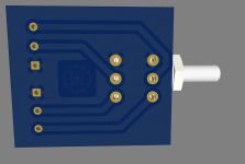
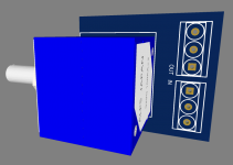
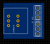
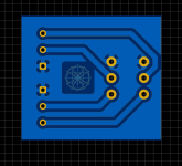
This is all standard stuff and can be done with something like this from Ali or a brand name one from the music shop
https://www.aliexpress.com/item/1005005062825028.html?spm=a2g0o.cart.0.0.570638daNdzeH5&mp=1

The difficulty is with how we use it. We already have tube based pres for our bass and mics, as well as tube based headphone amps. There are duplicate functions in the pre stages of a regular interface and our pres too

Aims
Bass player - a mono audio line into DAW for bass and one for his mic. MIDI foot control of live effects for the snare on the sequencer pads. MIDI foot control of a VST synth arp in the DAW. MIDI foot control of the effects for other channels. A personal headphone channel from the DAW

Flute player - a mic line for her into the DAW and a stereo line for her vintage keyboard. A personal headphone channel from the DAW

iOS synth player - a mic line for her into the DAW. A personal headphone channel from the DAW

To save some money and to avoid duplicating all the pre stages, I am inclined to try a high quality external HT sound card that has three pairs of audio out RCAs to feed the three headphone amps. Use the analog out on the PC internal sound card for the master monitor and the analog input pair for each mic. An ADC for the vintage keyboard on the optical in of the internal sound card

This leaves one mic short, but maybe a USB mic can be used here?

I have been able to previously use asio4all to run headphone outs and monitor and master outs on a PC with virtual DJ before, so FL should be more configurable

I need a plan for the foot controls. That's echo and delay effects for the snare, effects and control of an arp, effects for the other channels. Maybe four rows of expression controls on a custom board? I am thinking that a rocker style foot control will allow the amount dialled to stay there like a knob. Rotary encoders on their sides, for delay, echo and levels, plus foot buttons for arp switching?

I look forward to hearing thoughts on the audio routing and MIDI setup

Topping D50 salvage

Hi All. I've got a Topping D50 with a burnt out DC/DC converter. I think I can replace the converter chip TPS65130, but more concerned with putting in new resistors, which is going to be very fiddly, and what damage has been done to the circuit board. Rather than the replacement and repair route is there a way of bypassing the whole DC/DC convertor with a separate unit?
I'm a novice but happy to try a bit of soldering/ desoldering for the learning experience.
The unit still powers on ok, but no sound output. What do you think? Seem to be a lot of valuable components here, is there any way to salvage something, or is this just a coffee mat?

Attachments

  • IMG_20230211_120930447.jpg
    IMG_20230211_120930447.jpg
    580.7 KB · Views: 238
  • IMG_20230212_131815463_HDR.jpg
    IMG_20230212_131815463_HDR.jpg
    434.2 KB · Views: 229

For Sale Audiotechnology 18H52-17-06-SD several pairs

Hello. I have some Audiotechnology 18H52-17-06-SD midwoofer pairs (up to 5 pairs) in the shelf that will be for sale for another DIYER to use them. Please, read the whole thread.

18H52-17-06-SD with trimmed frame (made in AT factory). Intended to be used in D'apollito arrangement, I have up to 3 pairs for sale. Original packaging. Very good condition.
2 units: 330€
4 units: 625€
6 units: 900€


18H52-17-06-SD standard frame. I have 2 pairs: one of them is 4 Ohm VC and one another is 8 ohm VC. Very good condition both. Original packaging
2 units (4 or 8 ohms): 350€


All the drivers had been tested and used. There are some screw marks in the mounting holes but nothing visible after screw
Prices doesn't include PP feed not shipping.

Bryston 3B-ST and 2B, need help with bias and offset

Greetings!
I had no luck getting help from Bryston, not sure why they are not responding. I am preparing these Bryston amps for an install at a venue and I need to make sure they are running properly. So, I am reaching out for help here.

I have a working 3B-ST and need some help with the following: where and how do I check and set the "bias" and "offset"?
Also, I have a used 2B-LP and need to confirm the proper "bias" voltage, as it seems to be running hot.
Also, I have a used 3B (non ST), need to confirm the "bias" voltage.

Thanks!

Looking For a Good Function Generator to Produce Square waves

I have been reading but haven't been able to wrap my brain around what to get. I would like a piece of equipment to test square waves at 1khz and 10khz for testing amplifiers for oscillation etc.

Looking for something in the $100-$200 range. I was hoping some of you may have some good suggestions. Maybe something I can order on Amazon. Sorry for the newb request. This will be my first Function generator and I feel like I am running around in circles trying to get something to produce a nice square wave to test with.

Thank you!

G. Rankin 45 DCCCS amp mods

I build this amp years ago and it was excellent! I want to have another go at it with a few changes, like doing away with the ECL82, this question is about the pentode section forming the CCS, other than a socket change and filament current, can I swop in a 6v6g, with no other changes. want to use a ST tube the same size as a 45, so there may be other options. Thanks John

Attachments

  • 20221221_115404.jpg
    20221221_115404.jpg
    344.2 KB · Views: 188

Bottom plate for tube build?

I am building a tube power amp and I am doing the classic aluminum top plate and wood sides.

On these builds do people usually also add a bottom plate to enclose the electronics and seal up the amp, or is the bottom left “open”?

I can see pros and cons of both. If I added a bottom plate I’d have to perform the extra work and have it cut out so there is ventilation.

SMPS powered small cl. A amp

Couple of months ago I got two nice SMPSs (12V/6A) originating from discarded computer network equipment and since they are nice, clean and quiet (less than 1mV of 55kHz noise after output filter, at full load) I thought I could use them as a power supply for a small class A power amp (I never used SMPS in a power amp before).
Just to test it I chose the composite topology - OpAmp at input and source follower with Lateral MOSFETs at output. AD823 was my choice because it swings rail to rail. Also it has JFET input (low offset, high Zin) and later I discovered that it sounds really nice in this combination.
To extend the voltage swing of the output stage I bootstrapped the MOSFETs' Gates with C2, C6 so the amp clips at 23Vpp with 24.4V power voltage (the rails are actually 12,2V) which translates into 8W @ 8R i.e. 16W @ 4R.
Output MOSFETs are biased through voltage dividers (P1+R10)/R12 and (P2+R9)/R11.
Biasing starts with max. value of pots (lowest bias). Pots are turned slowly and alternatively (like described in F5 manual) until we reach (depending on your heatsinks and speakers) Id of about 0.5 - 0.7A and DC offset at the output of 0mV (put 0R1 serially in one of the power rails and measure 50-70mV accross it. Remove it after biasing). We use Laterals without source resistors so we can exploit their square law transfer characteristic and the exact bias current value is not that important but you can play with it.
DC offset is very stable, thanks to OpAmp's feedback loop which includes MOSFETs (meaning very low Zout i.e. high damping factor too). The pic shows MOSFETs and voltage dividers as point to point build on the heatsink and the chip is on the perfboard by the PSU so I adjusted the bias and the DC offset before I powered the chip and it stayed stable after inclusion into feedback loop. C5 (SMD) is soldered directly between the chip socket's pins. All electrolytic caps are 16V Japan made NIC (NRSG series - very low impedance): NRSG Series Page
The amp is very stable and fast and sounds much better than I expected. Most of all, it's an easy build. Have fun with it...
Pics show:
- Square wave 15V_pp 20 kHz @ 5R load (5V/div, 20uS/div)
- Square wave 15V_pp 20 kHz with 100nF pure capacitive load (5V/div, 20uS/div)
- Square wave 15V_pp 90 kHz @ 5R load (5V/div, 5uS/div)
- Prototype build (when put together the amp measures 22cm x 22cm x 10cm - heatsinks are 22cm x 10cm x 4 cm and they go to about 20 degrees C. above the ambient temp.)
- Schematic diagram (every channel has its own power rails filter)
- Hard clipping of 20 kHz triangle wave (5V/div, 20uS/div)


P.S. Dobrivoje, thank you for the heatsinks ! :wave2:

Attachments

  • 15Vpp 20 kHz @ 5R.jpeg
    15Vpp 20 kHz @ 5R.jpeg
    24.9 KB · Views: 1,693
  • 15Vpp 20 kHz @ 100nF.jpeg
    15Vpp 20 kHz @ 100nF.jpeg
    24.1 KB · Views: 1,667
  • 15Vpp 90 kHz @ 5R.jpeg
    15Vpp 90 kHz @ 5R.jpeg
    24.4 KB · Views: 1,744
  • Prototype.jpg
    Prototype.jpg
    759 KB · Views: 2,124
  • SCH.jpg
    SCH.jpg
    89.3 KB · Views: 2,249
  • Triangle Hard Clip 20 kHz @ 5R.jpeg
    Triangle Hard Clip 20 kHz @ 5R.jpeg
    22.8 KB · Views: 1,481

FS Sony Vfet set from TA-5650

I dismantle these from a broken amp many years ago. Not intend to do anything on it.

I would like to sell USD250 include ship. Paypal family with no fee.

Im not very familiar on these, so i only did a rough measurement on the 2 legs. 7 pieces of them measure a legs with chasis have 1 to 100 ohm random. one of them both leg measure have 1 ohms n 20 ohms.

Please evaluate on these before buying and i provide no return and warranty. thanks

Attachments

  • 1676551060365.jpg
    1676551060365.jpg
    209.6 KB · Views: 175

Big dip between active and passive filter around crossingpoint?

Hello folks

Have build a DIY MTM with 2 x Audax HM210Z10 and a Mundorf AMT29CM1.1.
Woofer is 3 X Peerlees XXLS 12 inch per side vented in 102 liter netto, tuned at 22 hz

Xoverpoints are 340 and 1850 Hz, and i use a Active filter for both high and low feeding 2 stereoamps.
So woofers get all under 340 hz direct from active filter/amp, and midrange/top get everething over 340 hz from active filter/amp, but have a highpass filter.

Audax midrange have a 2 order filter and Mundorf AMT have a 3 order filter (from 1850 hz).

The measurements over 1K looks quite good, but i have a terrible deep long 19 dB dip from about 180-680 hz?
Don´t know where to start trubbleshooting?

Can´t do much under 340 hz sinse the active filter does "everything" for the woofers, and don´t understand why midrange curve is "so bad" from 340-680 hz, but same time is good from 1K ?

Anyone have some suggestions?
This is ihow it looks in XSIM, and yesterdays measurements.

Best regards John

Attachments

  • Audax_Mundorf xover.png
    Audax_Mundorf xover.png
    124.1 KB · Views: 160
  • 190 to 680 hz problem.jpg
    190 to 680 hz problem.jpg
    122.1 KB · Views: 175
  • R speaker 1M No smoothing.jpg
    R speaker 1M No smoothing.jpg
    189.3 KB · Views: 175

"The Wire AMP" Class A/AB Power Amplifier based on the LME49830 with Lateral Mosfets

"The Wire AMP" Class A/AB Power Amplifier based on the LME49830 with Lateral Mosfets

A new run of these boards is now available! Please see the following thread for details:

http://www.diyaudio.com/forums/soli...ble-here-bal-bal-se-se-lpuhp.html#post3516741

Hi Guys,

There's a new addition to "The Wire" series of projects I've been working on lately.

It's push-pull amplifier based on the LME49830 front end which drives a pair of ACD101NDD and ACD103PDD lateral mosfets. It's immensely versatile in that you can run essentially any rail voltage from about +/- 10V up to about +/-90V on the mosfets and get anywhere from 1W to 400W of output depending on the load and the rails. This is an amp that can be tailored to any situation.

You can also run the amp in class A, class AB, or class B if that's your thing.

For the input, you can run either fully balance, or with just one 0R jumper it can be configured for SE input. You can run the amplifier AC or DC coupled. There are separate supply options for running the LME49830 on higher rails than the mosfets which improves efficiency and allows for a good regulated supply for the front end. Alternatively, with a pair of 0R jumpers, you can run just a single +/- supply for both the LME and the mosfets.

The board is small enough to fit pretty much anywhere, and all you need to provide is the power supply and the heatsink! I've even got an optional regulated supply board for the LME section.

I've attached the schematic, the Excel worksheet to calculate power outputs and rails, along with the layout and a BOM.

The PCB will be a 3 layer design with a ground plane in the middle and signal routing on either side. The LME has its own heatsink and the two mosfets are mounted on a user supplied sink off the end of the board. The board measures 2.45" by 1.6" and has all the required mounting points.

I will also be running a kit with this that includes all of the parts required to build a complete amplifier. All the user will need to supply is the main heatsink and the power supply.

PCB's are going to be $12 per channel, and a full kit including all 0.1% thin film resistors, and the best caps available for this application will be $78 per channel. I've attached the price list for the amplifier kit which contains all the details.

There will be 50 boards made available, and it will be first come first serve. Please post here if you're interested in a just a board, or a board and a kit, along with how many of each. Any technical question are welcome as well!

Measurements to follow!


EDIT - 27/05/2012

The schematic and layout below are incorrect. For the updated information, along with the assembly guide, please see this post:

http://www.diyaudio.com/forums/soli...-lme49830-lateral-mosfets-75.html#post2920157

Cheers,
Owen

Attachments

Projects by fanatics, for fanatics
Get answers and advice for everyone wanting to learn the art of audio.
Join the Community
507,671
Members
7,883,635
Messages

Filter

Forum Statistics

Threads
405,998
Messages
7,883,635
Members
507,671
Latest member
rooomn