For stereo imaging, do only L-R differences matter ?

Some argue that for accurate stereo imaging, basically only the differences between the left and right speakers matters and not the absolute flatness of the SPL function.

I think this hypothesis is testable. This test distinguishes three situations:
A) Both channels play without disturbance
B) Both channels are disturbed identically
C) The channels are disturbed differently

In these three situations, the sound (music) is evaluated for stereo separation. This can be blind tested.
If situations A and B have approximately the same separation and C clearly less, than the hypothesis is true.
If situation A is clearly better than both B and C the hypothesis is not true.
It is also possible that the results are not conclusive.

The distortions can perhaps consist of a some dips in the SPL (perhaps 2 to 5 dips, -6 dB, Q=2 between 500 Hz and 5 kHz).
If the distortion have to be identical, the dips must be the same left and right and put on the same frequencies. If the channels are disturbed differently, the dips remain the same but are put on different frequencies.

Necessary for the tests are a good speaker system and a dsp between sound source and power amplifier. The dsp should be set up in a way that it is easy to switch between the three situations.

Hafler preamp upgrades

I have this very rare preamp, is a Rockford Fosgate RF200 or also it was sold as Hafler JF200.
Is a op amp preamp
2 5532
4 TL072
6 LM833
IC LM393

The preamp got a good review, is there any room for improvements ?
I am open to suggestions

Are those red candy type of capacitors, film polypropylene ?

Attachments

  • JF200_RF200_PC-007_sch.pdf
    JF200_RF200_PC-007_sch.pdf
    157.4 KB · Views: 76
  • IMG_0158.JPG
    IMG_0158.JPG
    411.4 KB · Views: 73
  • IMG_0159.JPG
    IMG_0159.JPG
    521.2 KB · Views: 72
  • IMG_0160.JPG
    IMG_0160.JPG
    358.6 KB · Views: 63
  • IMG_0161.JPG
    IMG_0161.JPG
    340.8 KB · Views: 72
  • IMG_0162.JPG
    IMG_0162.JPG
    380 KB · Views: 63
  • IMG_0163.JPG
    IMG_0163.JPG
    544.9 KB · Views: 66
  • IMG_0164.JPG
    IMG_0164.JPG
    417.1 KB · Views: 66
  • IMG_0165.JPG
    IMG_0165.JPG
    327.5 KB · Views: 63
  • IMG_0166.JPG
    IMG_0166.JPG
    536.7 KB · Views: 61
  • IMG_0167.JPG
    IMG_0167.JPG
    282.8 KB · Views: 58
  • IMG_0168.JPG
    IMG_0168.JPG
    496.7 KB · Views: 58
  • IMG_0169.JPG
    IMG_0169.JPG
    484.8 KB · Views: 67
  • IMG_0170.JPG
    IMG_0170.JPG
    525.4 KB · Views: 62
  • IMG_0171.JPG
    IMG_0171.JPG
    542.5 KB · Views: 74
  • Audio magazine rf2000 review.pdf
    Audio magazine rf2000 review.pdf
    466 KB · Views: 73

For Sale Sanken 2SA1859A and 2SC4883A NOS

I bought these several years back when I had some restoration to do and bought all that BDENT had in stock. Gotta clear some of this stuff out. Don't get beat up by buying knock-offs and fakes from who knows where. I have 47 of each. Many MFGR's used these like Sansui, Marantz etc.... I know many of you like to keep the original components. I'll be listing more hard to find parts soon.

PayPal FF preferred.

$4.00 each with free shipping on orders of 10 or more. Same day shipping if purchased before my mailman comes (about noon). US Shipping only


Sanken.jpg

Advice on online speaker cable connectors

I need to be able to disconnect 3 speaker cables that run from 2 Neutrik Speakon panel connectors.
This is necessary when I remove the rear enclosures of my SH50 synergy horns.

I will remove them to halve the cabinet weight when I need to move them around.

Currently the cables are soldered to the Neutrik spade terminals and ditto to the drivers. Long enough to slow the rear enclosure to be lifted and dropped m into place.

I'm using 1 X 2 way neutrik plug and 1 X 1 way.

What simple robust, good quality, inexpensive inline connectors could be recommended for this?

I've looked at Neutrik and clone offerings, they are all a bit bulky and might need taping or other to stop them rattling around?

Something positive clicking together and perhaps silver plated like Neutriks.

I would need 6.

Other ideas welcome.

BYD17D Replacement options.

I'm currently trying to repair a primare integrated.
I need 8x BYD17D or substitutes for the power supply section.
These are Controlled avalanche rectifiers.
200v 1.5amp in SOD87 package.
Att is the pdf for said device.
I can only find places that list them as obsolete with no recommended alternatives.

Help, Ta 🙂

Attachments

Cascading two low-pass filters

Has anyone ever seen this kind of loudspeaker's crossovers in this picture?

calc_cr_12db.gif


It looks like there are two second-order low-pass filters cascading. I'm not sure if it is aimed for creating the half-way system or not, i.e., 2.5 or 3.5-way speaker system.

If it is meant for the half-way system, then, are there any formula for calculating those L1, C1, L2, C2 parameters? Assume WF#1 and WF#2 are identical.

Problem with dual supply amplifier (triple emitter follower)

Hi, i stumbled on a schematic for a class A amplifier with very low output distortuion (0.008% at MAX power).

I picked this schematic from a book, but is seems like there is something WRONG in it!!!!

I built this circuit two times, and two times it had the SAME problem:

When i power the negative rail, the output of the amplifier is just DC voltage. If i power the positive rail, it does not care at all (nothing happens). If i power both, still always DC voltage on the output.

WHY is that!!!?

It's not even built in a prototype board but on a dual layer PCB that i very carefully designed on PC, then i ordered it online.

Two attempts, two failures.

Can you understand if this schematic is actually wrong?

Thank you.

Attachments

  • IMG_20240526_151456.jpg
    IMG_20240526_151456.jpg
    271.3 KB · Views: 383

Please welcome, me

Hi diy'ers

I've been a lurker for a long time and found many solutions on your forum. I've never been a user though.

I have been a user on audiosciencereview for many years where I've learnt a lot about audio measurements. I think maybe, through learning this, I've come to realize how flawed the concept often is carried out in the actual reviews and following viewpoints on the site.

There is no room for proper discussion about this. You can either do exactly what the owner and his enforcers tell you to do with no questions asked or you can get the hard treatment with no respect to what you might else have accomplished on the forum, how many you've helped etc. I've seen this happen to many prominent users over the years.
They pride themselves for being scientifical. It's mostly superficial knowledge and echo chambering of the largest voices opinions circling around. In my mind this is not much better than the audiophiles discussing cable risers.
I come with a mixed engineering background; both electrical and mechanical b.sc. with thirty years of experience. I hope to contribute to the topics I find interesting here.

/Brad
  • Like
Reactions: Gulo_Gulo

Choosing a top for 3 way

Hi there everyone. Its been a while since I took on any audio projects and have a few piled up I want to chip away at.

One burning question is regarding my 3 way setup. I run a Driverack 260 and active setup and am planning to make a large 3 way speaker and my selected mid is JBL 2251J which is a 10" driver and a JBL 2245 for bass. Kind of thinking in vein of the 4345.

For HF I have a few different drivers and guides on hand and was wondering if anyone had any guidance... Not sure what will work or if any will work well due to the mid size, as I think most of the CD waveguides are meant to mate to a 12".

The drivers I have on hand are a pair of JBL/Selenium D220ti OMF bolt on and a pair of Celestion CDX1-1745 which were originally for another project but may use if applicable and suited.

My waveguides are the B52 QSC clone, DDS CFD1-90 Pro, and also a threaded set of Dayton 6512 that I was considering maybe a JBL 2408H2 (others are NLA).

Curious if anyone had any guidance in selecting a HF unit for a project like this. Thanks in advance.

Hello World!

I'm out of Indiana, mechanical engineer by day. I lucked into some vintage audio equipment about 10 years ago and have been hooked on HiFi ever since. I dabbled in building a little with EPS foam exciter speakers and an equalizer. The results were good, but now I'm looking to build weird and/or 3D printed speakers with high wife approval factor.

Acoustically small horn vs flared vent

Hi all,
I am designing a subwoofer for 20-80hz region to complete a sound system I’ve bought, I’ve got a great interest for horns but think my space requirements are too small for a folded or tapped horn, but I really want that aggressive look of folded horns/scoops/bph
my plan is to design a 6th order band pass enclosure with rectangular ports flaring i guess in a conical ish way- straight lines expanding to a larger mouth

I’m really struggling to find how to model this/ find forum posts or literature on how this affects port tuning, everything I’ve seen is for exponentially flared circular ports which only affects the air velocity, I’m not sure how the length and different volume of air will affect the tuning of the port. The only thing I can think of is plugging a bunch of differently flared boxes into akabak and see what happens but this will take days if not weeks as I’m not very proficient in akabak yet.

I’ve read the explanation on free speaker plans about bandpass enclosures under 1.67m in horn length but need some more help understanding before I can design

So: how does flaring a rectangular port change the tuning? With the different volume how does that affect the tuning? Does the vent have to be the same length, or does it have to be the same volume of air?

Thanks in advance, it’s a silly question I know☹️
  • Like
Reactions: Kravchenko_Audio

Hello there!

Hello from the Pacific Northwest! I'm getting back into audio after a two-decade hiatus. I am planning a 2-channel setup for semi-serious music listening, and I've also put together a home theater system whose foundational principles were to sound decent and be super inexpensive while meeting current AV standards. Looking forward to meet folks around here and hopefully exchange good info / ideas!

GZCA 12K-SPL DC offset

Really long story....in short

Amp came in with blown up capacitors in the class D output filtering, the ones 1uf 400v between the output terminals and ground. 10ohm 5W resistor was in bad condition too.
Replaced those.
Amp now has DC offset of approximately 20v which can NOT be fixed by the trim pot, it can fix only 1-2-3volts of difference not more. It plays, no protect, class D switching is present, but as You can imagine having 20v DC on a speaker = not good.

Seems like one of the amplifiers, in RED (it is full bridge class D) works with 20v-21v LESS than the other one in BLUE. These are the only differences I found between both amps driver IC's, pictures are attached. What I understand....when having a 150v rail, there should be aprox. 75v at each output terminal....now I do have 85v at the one and 65v at the other....not good. Connecting a load does not change the DC offset. How to fix this disbalance ?
One of the amps in this full bridge, the one in RED, with less voltage present, the low side outputs are warming up. 1 minutes of idle = 60-70degrees, high side stays normal/cool.
So i've put my effort in this RED "amp" where the heating up is happening, I do use the other one BLUE "amp" as a reference as it's not heating up.
What i've replaced so far - IRS20957s, both buffers (the 6 pin drivers), all of the 15v zeners, all of the MUR120 diodes, all the resistors near the driver/buffer, IC, zeners, all of output transistors. Parts are from reputable source. So even after changing all of this, there is NO single difference. It is exactly behaving the way it was before doing any work at it.

Any ideas ?
I will attached some of my draft measures.

Attachments

  • 11.jpg
    11.jpg
    530.7 KB · Views: 95
  • 12.jpg
    12.jpg
    584.5 KB · Views: 94
  • GZ12SPL.jpg
    GZ12SPL.jpg
    183.7 KB · Views: 102

Supercap/Goldcap - Replacement in my receiver after 14 years of daily use

Hello

After 14 years I decided to replace the supercap for my Denon AVR-1910.
It's a 1F, 5.5V Elko.
I just want to let you know what my measurements showed:

The capacitor now is loosing about 1V per day.
So, after 5.5 days it will be near to 0V if not charged.
The memory for the settings probably is lost earlier - I don't know it's critical voltage.

I hope this gives you a clue as to the ageing of these supercaps.

Best regards

Help choosing Purifi midrange

Hello everyone.

I want to replace my midrange speaker. Now I have an audiotechnology 18H52 17 06 cut at 300 and 3000 hz with a slope of 48db. The cut is digital with Dephonica software.

My candidates are the Purifi, but I don't know which model to choose.
PTT4.0M08-NFC-01
PTT4.0M08-NAC-03
PTT5.25X08-NFA-01
PTT6.5M08-NAA-08
PTT6.5M08-NFA-01

The upper cut must be a minimum of 2500 since I have a Raal 70-10. The woofer is a TAD1603 and can be cut higher than 300hz if necessary.

The impedance must be 8 Ohm.

The aspect that I value most is the detail.

I'm open to other speakers in that price range.

Thank you so much.
Greetings

intro - bitten by the hifi bug a long time ago

Hi fellow audio addicts,

I simply like good music of many different genre - preferably played on a (very) good system.
I've been bitten by the audio bug when exposed to better systems in a high-end show a long time ago - and it's been itching ever since.

I think there are levels of involvement in home / personal audio:
  • There are people who do not hear the difference between systems or they just do not care. From finance perspective, they are certainly the luckiest.
  • Then there are those who can hear the difference but still do not care much. Even luckier, I guess.
  • And finally those who can hear the difference and are vexed by anything inferior to the best that they have heard (which is of course, subjective, But that is fine, hearing - intricately refined as it is - is still subjective).

To my demise, I was mesmerised on the first hifi show of my life and - pleased by the revelation - immediately concluded that I have to have a B&W CDM-1 or build something from Vifa drivers. Lack of time led me to the B&W CDM-1.

I saved up for it, ordered it, took it home intoxicated by the fact of possession. Adrenaline rushing, I hooked it up with - I think - an UHER receiver, a Technics CD and some shoelaces made of copper ... aaaaand ... was of course taken aback by the lack of musicality or detail. "Not in the same league" is an expression but the experience wasn't even on the same planet. So starting off with an emotional rollercoaster, my journey begun and fortunately hasn't ended till today.

Since then, I've been walking the El Camino of hifi enthusiasts, going step-by-step, stocking up a few of everything. Never (ok, rarely) regretted any of it, I've always learnt something, getting closer and closer to the goal that can never be reached.
I've achieved an acceptable compromise years ago (with an actively driven biamped electrostatic speaker and able amplification (partly DIY), good cabling and sources. It did cost money of course - may be considerable - but it has never wrecked the family budget. I'm quite keen on getting a good price-performance ratio.

I'm more into DIY experimenting nowadays, currently after good desktop speakers that I can listen to while in home office. A small Fountek FR135EX project is on the way, but more to come, if circumstances allow.

All the best to the community; may your journey be enjoyable!

Recommendation for Forte 4 Review / Repair - Western NC Area

Hi Everyone -

My brother's Forte 4 lost the left channel after a power surge. I didn't have much for diagnostics while travelling, so I did what any responsible little brother would do... I gave it a VERY brief once over ... found a dud negative rail fuse... didn't see anything else suspect ... replaced the fuse ... and powered it up. The left channel came back up / warmed up.

I didn't have proper tools nor schematics while I was on vacation to do an in-depth review of the amp. I saw that it warmed up, and that the offset was <20mV. I sent him on his way. So, when he got it home, he hooked it up. The volume was lower on that channel, and then the replacement fuse blew after a few minutes.

So, someone with the proper tools and the schematics / service manual will need to give it a look. I had John Soderberg go through it many years ago and do all the updates etc. I can definitely send it back out to John if necessary.

However, I sent it to John before I ever became active in DIY. I'd have my brother send it to me, but I don't have schematics or a service manual. Also, if any of the parts need replacement, I may not have easy access to replacements.

Plus, it's is pride and joy (as it should be). So, I'd prefer to have someone that knows these amps go through it.

tl;dr - Does anyone know someone they'd vouch for in the Western NC area (near Asheville) or within a few hours drive that could repair the amp? If not, I'll have him send it off to John.

Note - My brother found https://ncstereoman.com/info/category/home/page/3/

Heck if any of you are willing to give it a looksee, I'd be more than grateful.

Thanks in advance.

Huge 2 x 18" Under Floor Subwoofer, or am I going nuts?

Hello!

I would love to hear your opinions on a project that I have in mind, which, however, may not make any sense at all... and feel free to tell me if that is the case 🙂

I am remodeling my sub-terrain wood workshop, and there is a hole in the floor from a previous heater installation, here is a close-up of that hole with its dimensions (ca. 1.5 x 2 meters, 0.5 meters deep):

shot-2024-07-11_23-14-51.jpg


It's all cement, just like the workshop floor itself. But since it is uneven, the plan is to cover the entire cement floor with a wood plank floor (leveled, sitting on shimmed beams).

But when I thought about something useful to do with this hole, the best idea I had was (at least so I think), to put a subwoofer in there.

I have two 18" McCauley 6174, which are left over from another project. For these I am planning to build a large subwoofer box (according to their T/S parameters).

Now my questions are:

  • Does it make any sense at all?
  • Would two much sound get lost, with the speakers under a wooden floor? Maybe cut slots into the wooden floor?
  • Should I worry much about dust, and maybe build the box in a way that the speakers are not directly exposed, maybe a bandpass design?

- If all else fails... any better ideas for this hole? Here is a drawing of what the finished workshop shall look like, the whole is under the long workbench, where the dimensions are still drawn:

shot-2024-07-11_23-20-01.jpg


Thanks for any input!

High Pass Filter (HPF) what is better, big Resistor or big Capacitor?

Hi

Does anybody know what is better to choose for a High Pass Filter (Mic Preamp):

Big Capacitor value, small Resistor value?
or Small Capacitor value, big Resistoe value?
Or use as special Resistor value und adjust the Capacitor for the needed Frequency?

I don't have the Tools to check it by myself at home. Otherwise I would try and measure by myself ;-).

Best regards
Lukas

For Sale Technics SP-10 MK2 MKII NEW Torlon Thrust Pad and Si3Ni4 Ball Package Price

SOLD.

This is a package deal for a brand-new silicon nitride bearing ball and Woodsong Audio Torlon thrust pad for your Technics SP-10 MK I or MK II turntable.

I ordered several thrust pads from WA (the only supplier at this time, I believe), and several new balls to supply a few friends and myself for the turntables we are all servicing/rebuilding. I have one remaining set and am making it available to you at a discount. WA sells the thrust pads for $50 and the balls cost about $5-6 each.

Your price is SOLD including shipping in a padded envelope and PP fee (only within the continental US due to the hassle of Customs forms and higher shipping costs).

SP10_Ball_Pad.jpg

Help me to find the right 10” woofer for my 3way active

Hello all , long time in the forum but never wrote or post something.
First of all forgive my bad English , maybe that can be the reason I haven’t interact up until now but it seems I’m in a “dead end” and I need a little help, even some guidance .

So I’m all Sansui enthusiasts and I’m running a 3way active set up with AU-X11 amplifiers and a CD-10 active crossover. All equipment is fully restored and are running smoothly.

My drivers are :
Tweeter : Scanspeak 28mm Dome D2905/97000
Midrange : Morel soft Dome EM 1308
Woofer( subwoofer as described in their website ) : Visaton 8” TIW 200 XS in 30Lt cabinet .

I want to “up” my game at the low end, god forbids I have no complain from the Visaton driver but I think I need a 10” woofer …..
The Visaton in the 30Lt cabinet is tight, full and precise even at the lower volume level , I’m looking for a driver that can perform a bit better and match the quality of the other drivers .

I can not go bigger than 50lt but my budget can be high , not because I’m a rich guy but building speakers is not hobby and most likely those speakers will follow me for the coming 10 years .

Any suggestions will be much appreciated and thank you in advance for that .
Again… sorry for my bad and poor English.
  • Like
Reactions: Jcris

Title: Converting David Clark Headset Analog Output to USB

Hello everyone,

I have a David Clark (H9940) headset with the following pin configuration:
https://www.davidclarkcompany.com/files/partslists/pdf/PL19539P-95.pdf

  • RT ear
  • Ground
  • LT ear
  • Sens
  • Mic Hi
  • Mic Low
  • Shield
I want to convert the analog output of this headset to a USB connection. From my research, I understand that I need an ADC board like the Behringer U-Control UCA222 to accomplish this.

My plan is to wire the pins from the headset to RCA plugs that can connect to the UCA222. However, I'm looking for some guidance on the specifics:

  1. How should I wire the RT ear, LT ear, and ground to the RCA plugs?
  2. How do I handle the microphone signals (Mic Hi, Mic Low, and Shield) in this setup?
  3. Are there any additional components or considerations I should be aware of to ensure proper functionality?
Additionally, I know that the headset requires external voltage and impedance control for the microphone to function correctly. Could someone provide details on:

  1. The required voltage levels for the microphone input.
  2. How to implement impedance control in this configuration.
Any advice, wiring diagrams, or tips from those who have done a similar conversion would be greatly appreciated!

Thanks in advance for your help!

Cathodyne tube line pre (cont'd)

Thanks to Schmitz77 for sparking my interest on the subject,

I am still fascinated by unusual tube circuit (read Shindo) I started collecting various tube configuration of EF86, EF80 circuit.

The first circuit comes from this thread posted by Schmitz77 :
https://www.diyaudio.com/community/threads/cathodyne-tube-line-pre.355172/

I went a little further and made a ltspice sketch and sim

1720431115936.png


FYI this is only the line stage, I'll concentrate on the phono stage later.


The most valuable info came from Stereophile, as Mr Dudley wrote :

- "The C3m is also capable of very high gain, but Ken Shindo puts it to a different sort of use: In the Vosne-Romanee, the Siemens tube functions as a resistance-coupled phase inverter, the output of which appears across the anode and the cathode."

- "The now-balanced signals for the left and right channels are directed to that pair of vintage output transformers, with DC blocking along the way by those large, lovely, and similarly ancient Sprague oil caps."

- "We brought up the volume just to the point of clipping and noted an output of approximately 5.5V RMS (which translates to just under 8V peak, possibly explaining the output level spec provided for the V-R on the Shindo site)"


From a theoretical standpoint, the split phase phase inverter comes from this reference (chap 10, page 217)
1720431560183.png


Anyways, I'm thinking building this project in the future and I wanted to know if anyone can give me some pointers on what to look for next,

I did a simulation on the frequency response, and I don't think it looks right,

Have fun fellow DIYers!

Oli

(I can link the EF80 and C3m Ltspice data I used for my schematic)

Attachments

How expensive can an Econowave be?

This topic came up on another thread about the best 1” horn drivers. https://www.diyaudio.com/community/threads/best-1-compression-drivers-compact-1-horns-2024.410465/

Then marco_gea posted “The answer is still the same... the "best" is still probably: https://www.proaudiodesign.com/products/tad-td-2002

So at $3,000 a pop I was wondering how expensive can an ECONOwave be? Aside from custom shop work or one time productions, what are we looking at for cost is no object two way horn tweeter loudspeaker?

Clients changed their minds…now what?

IMG_2151.jpeg
So originally, they were going to keep the tower speakers shown to the left and right,……..but now they would like to eliminate them and integrate the mains into the enclosure. This is a modular built and the 70” screen is on an electronic lift that lowers into the cab when not used. For reference, the enclosure is 75” across and 34” tall. I REALLY don’t want to go back to square one with this and I’ve convinced them to add two thin line sources to the sides of the screen that will attach to the lift………but that creates a new set of challenges as I’ve only got 5.5 inches to work with on either side and 4” of depth!!!

I‘d like to scratch my own itch and do something OB/dipole…….there‘s nearly 8 ft of space behind there with a stairwell…….an OB would really make for an incredible soundstage…….but I’d need the OB to play down 60hz or so to blend with the subs. How am I gonna do that OB limited to 5 inch woofers?
  • Like
Reactions: stv

Pass DIY Front Panels

Dear All,

Can I make a petition to make available the following front panels from the DIYAudio store or modushop not only as part of a kit ? I made several projects with the 4U chassis and those will really give a wonderful look and give the right cretid to the designer.

https://modushop.biz/site/index.php...ct&search=passdiy&syclid=cqf3er4om04s73fng5o0

Regards,

D.

Attachments

  • FrontPassDiy-1000x1000w.jpg
    FrontPassDiy-1000x1000w.jpg
    100.2 KB · Views: 119
  • Like
Reactions: ronex

Mark Audio Alpair 10.3 Bookshelf Reflex Monitor

Hello dear DIY Forum members!

As a new member, I would like to introduce myself. My name is Gerd and I live on the southern, outer green belt of Cologne, near the Rhine.

How I found the DIY Audio Forum – through reports/articles about Mark Audio speakers.

What have I planned? And that would almost answer the question of where a decision-making aid would not be bad:

I intend to build a reflex shelf speaker with a Mark Audio Alpair 10. 3 with the sonic orientation of a monitor speaker which displays clean 48 - 50 Hz.

Thanks for the tips!

Kind regards Gerd

For Sale UK Monacor DT99 pair

For sale pair of DT-99. Came in a pair of DIY speakers I bought off eBay and seem to be pretty much as new. Both measure same DCR.
Look like new . Not boxed but I will find a suitable box for them. Probably a tweeter box from SB or similar
£25 plus postage
Thanks

Attachments

  • IMG20231210144413.jpg
    IMG20231210144413.jpg
    488.6 KB · Views: 84
  • IMG20231210144423.jpg
    IMG20231210144423.jpg
    398.9 KB · Views: 75
  • IMG20231210144702.jpg
    IMG20231210144702.jpg
    515.3 KB · Views: 81

For Sale UK SB23NACS45-8 pair

New in box never used. I seem to have been sat on these for a couple years but they might as well go. I have a few RS225s which are my chosen 8" now.

Postage on application, will be at cost. Come in original boxes and packaging.

Sell the pair for the price of 1 new.
£115 plus delivery .
Thanks

Attachments

  • IMG20231210143735.jpg
    IMG20231210143735.jpg
    361 KB · Views: 65
  • IMG20231210143802.jpg
    IMG20231210143802.jpg
    426.7 KB · Views: 61
  • IMG20231210143817.jpg
    IMG20231210143817.jpg
    353.1 KB · Views: 65
  • IMG20231210143859.jpg
    IMG20231210143859.jpg
    379.1 KB · Views: 67
  • IMG20231210143926.jpg
    IMG20231210143926.jpg
    402.1 KB · Views: 72
  • IMG20231210143929.jpg
    IMG20231210143929.jpg
    358.9 KB · Views: 69
  • IMG20231210143958.jpg
    IMG20231210143958.jpg
    221.6 KB · Views: 67
  • IMG20231210144049.jpg
    IMG20231210144049.jpg
    327.8 KB · Views: 64
  • IMG20231210144104.jpg
    IMG20231210144104.jpg
    429.2 KB · Views: 66
  • IMG20231210144118.jpg
    IMG20231210144118.jpg
    326.7 KB · Views: 70
  • IMG20231210144125.jpg
    IMG20231210144125.jpg
    252 KB · Views: 65

For Sale SB Acoustics SB15NRXC30-8 pair

A pair of these for sale. Barely used. I went with MCA15 instead as needed purely mid range. One has OE box but for some reason I've misplaced the other. Has the original plastic guard to cover the cones. If I find the box obviously shall come in that.
I managed to nick the surround of one of them. Don't ask how. It is barely visible and if used as a midrange it wouldn't even open up . I put a small amount of PVA to heal it and it is nigh on invisible. Took me ages to find it to photograph. I'm confident it is of zero concern.
£60 plus postage

Attachments

  • IMG20240428093743.jpg
    IMG20240428093743.jpg
    368.6 KB · Views: 86
  • IMG20240428093802.jpg
    IMG20240428093802.jpg
    441.6 KB · Views: 78
  • IMG20240428093810.jpg
    IMG20240428093810.jpg
    474.4 KB · Views: 79
  • IMG20240428093837.jpg
    IMG20240428093837.jpg
    450.4 KB · Views: 86
  • IMG20240428094019.jpg
    IMG20240428094019.jpg
    273.4 KB · Views: 75
  • IMG20240428094032.jpg
    IMG20240428094032.jpg
    302.3 KB · Views: 79
  • IMG20240428094058.jpg
    IMG20240428094058.jpg
    254.7 KB · Views: 74

For Sale SEAS 22TAF/G pair UK

Pair of tweeters for sale. Bought off a gentleman on here along with some Seas MCA15RCY.
Didn't use them in the end. They have been used and soldered previous to my ownership
Both measure 4.8r
£45 plus post.
Thanks

Attachments

  • IMG20240504124220.jpg
    IMG20240504124220.jpg
    159.9 KB · Views: 62
  • IMG20240504124029.jpg
    IMG20240504124029.jpg
    411.6 KB · Views: 50
  • IMG20240504124116.jpg
    IMG20240504124116.jpg
    445 KB · Views: 62
  • IMG20240504124123.jpg
    IMG20240504124123.jpg
    454.8 KB · Views: 53
  • IMG20240504124213.jpg
    IMG20240504124213.jpg
    163.9 KB · Views: 59

NAD 2200 overheating transistor

This 2200 has been quite problematic. I have done my usual upgrades (www.quirkaudio.com), and in this case I have been chasing a set of problems on the left channel.
The current state is that all electro caps have been replaced all the transistors from Q201to Q333, and Q327, Q325 and Q331 have been replaced as have a number of diodes, including D309/D311 and D301/D303, so now the unit comes out of protection, however Q305 gets very hot meaning their is excessive current draw.

Q305 is now a KSC3503D, which I have used mnay times here.

On measuring R307 there is 0.7v across this resistor, whereas on the right channel on R310 it is 0v, and across R303 there is 0.29v, whereas on R304 it is 0v. On R377 there is 0v the same as R378, so my assumption is that the problem is not on the output side. All the main outputs test fine, Q311 had a low Hfe and was replaced with a new 1302.

When I measure across R331 I have 1.5v, whereas on R332 it is 0v. The two reference points at D309 and D311 should be +1.77v and -1.77v respectively, whereas they are 2.2v and -1.5v. The base of Q211 is 8.7v and all the other voltages on the circuit are correct.

I have attached the circuit and any thoughts are appreciated- this has me quite puzzled.


Peter

Attachments

Active 4-way with reaction cancelling woofers

In recent threads:

https://www.diyaudio.com/community/...crossover-frequency-in-the-near-field.401809/
https://www.diyaudio.com/community/...er-w-pd-21-drivers.402264/page-5#post-7433034


there is some discussion of the benefits of side-firing woofers. So I thought I would describe a recently completed build of mine which employs this method of woofer mounting. I have borrowed ideas from past commercial loudspeakers such as the AR9, NHT 3.3, various vintage Allison Acoustics models.

These are the features of my build that are unusual from a typical commercial enclosure:

1. Separate isolated sub-woofer enclosure, with reaction cancelling drivers.

2. 2” edge round-overs for diffraction effects control.

3. Low sub-woofer position for enhanced room boundary bass re-inforcement.

4. Tri-laminate layer (mdf/mdf/hardboard) 1.25” panels for increased rigidity.

The drivers chosen are:
sub-woofer 8" SB23MFCL45-8 (x2 in parallel), mid-woofer 5” SB15CRC30-8, upper-mid 4” SB12MNRX2-4, tweeter SB26STAC-C000-4.
I have a great respect for SB Acoustics drivers. They have great build quality, good performance and are affordable. My previous builds have used ScanSpeak drivers, but ScanSpeak prices have increased beyond my comfort zone for DIY, and I find the SB range comparable in performance. The SB drivers are affordable and offer a wide range of cone materials in the same driver format so that they can be compared to decide on a preference.
The 4” SB12MNRX2-4 upper-mid is the only dedicated mid-range driver in the standard SB range, with shortened voice coil and linear travel compared to their 4” mid-woofers and is suitable for a 4-way, where it can be high-passed crossed over well above the bass frequencies.
The 5” SB15CRC30-8 mid-woofer was chosen after comparing listening tests with the Norex and aluminium cone versions. The cone material is a Rohacell/carbon fibre laminate.

The upper enclosure is a compact sealed 3-way, decoupled from a sealed sub-woofer enclosure by 50mm diameter Sorbothane hemispheres. The chosen dimensions keep the tweeter-floor height at 1m, which is right for my listening position.

Attachments

  • IMG_0453.jpeg
    IMG_0453.jpeg
    829.8 KB · Views: 386

Learning by breaking things!

Hello, long-time lurker first time poster. I found this awesome forum while searching for pieces to fix a couple busted amps I picked up at a local garage sale. Well, they are busted now anyway! I'm using one as a plant stand and another as a platform to learn about solid state amps. I am enjoying the hobby so far. Currently stumped on something which I'll post about over in the solid-state forum. I'd like to get it working, since I already have a plant stand.

Best regards

Need some help with my woofer and its port. Getting huge rise in deep bass out of this Peerless 8"

What I did:
Took full measurements of my 3 including this Peerless 8" woofer here.
Took near field of woofer
Took near filed of port
Took far field of woofer
Aligned near field measurments SPL to the near field SPL so that I can use the far field measurement for my crossover design (mic never moved between measurement of the other 2 drivers so this should keep the SPL and phase aligned for crossing over purposes)

What I don't get:
1. I kind of understand the giant rise from the port as expected something like that but this seems excessive
2. Why the woofer near field starts to rise up dramatically as well around 100 hz

Is is possible that the port output leaked into the woofer near field measurement? Is is literally about 5 inches below the woofer and this would explain a lot

It is also VERY possible I do not know what I am doing with REW. If so, please let me know. I am very good at following directions and I tried very hard to follow the REW directions to the letter.

One last question..... Do I need to combine both the nearfield woofer and port measurements to accurately crossover the woofer with the mid? I would think the port acts almost as its own driver so its response would need to be added to that of the woofer, yes?

Attachments

Measurements and VituixCad Model Correlation

Sorry a bit of a long post but need to get some knowledge from the group before I spend too much more time on this.

I have taken a set of baseline measurements of my 3 my speaker in an anechoic chamber (chamber has a null at 60hz but above 200hz there is no need for gating, very clean data). The measurements taken were -
  • Microphone at the same position for all, 1m from centre of baffle at tweeter height.
  • I had the acoustic timing bleep turned on but this was played through the driver being measured (now I know that you need a second speaker for this to work properly, doh !) therefore all measurements start at 20ms which seems to suggest the data has no acoustic offset built in, is this correct?
  • I measured the Woofer (WO24P-4, 40L sealed stand mount monkey box), Mid (EM1308, includes a 39uF protection Cap) and Tweeter (ET448, Includes a 12uF protection Cap) at +/-90,75,60,45,30,20,10,0 degs on the horizontal axis. I did meaure the Mid and Tweeter withouth the protection Caps as well but will be running an active system with them included.
  • I also measured the individual drivers and also driver pairs (woofer/mid, mid/tweeter).
  • Finally, I did some nearfield measurments for the woofer both on tweeter axis and the woofer axis at 1cm, 30cm, 60cm and 1m.
Now the conundrum:

Using the pairs technique by loading the individual driver measurements and the paired data into VituixCad I can adjust the delays to make the summed individual match the pair data. This results in -

Woofer/Mid - Mid is -270uS which equates to 93mm this is not far from a geometric calculation using Pythagoras (88mm).
Mid/Tweeter - Tweeter is +20uS which equates to 6.9mm which again sounds about right for a dome mid and dome tweeter.

That said, I modeled up a crossover in VituixCad without adding the offset above, measured the combined speaker response (also with inverted mid to get nulls) and individual driver. The whole speaker model vs measured response matched very well and the step/impulse response also was pretty comparable. Which seems to suggest the data has the acoustic offset embedded in it and my method seems to be correct but something doesn't quite add up with respect to the acoustic offset.

So, the questions is what do I do with the offset data calculated with the pairs approach or have I measured the speaker incorrectly or have I lucked out on my measurements/modelling approach ? Any help will be very welcome and gratefully received, thanks in advance.

For info - if I add in the offsets as delays into VituixCad it is almost impossible to get the phases to line up between the Woofer and Mid.
As an aside after I did this comparison I slightly altered the VituixCad Model2a (2a1) by upping the Tweeter delay to 30uS and slightly changing to the High/Low pass which brought the phases into alignment right up to 15kHz, maintained the flat on axis response and maintained the deep nulls.

I can post the REW mdat files for the three drivers if anyone want to have a play.

Attached is a number of plots showing:
  • Woofer/Mid Offset at Mid= -270uS
  • Mid/Tweeter Offset at Tweeter = +20uS
  • VituixCad Model2a (my model designation)
  • VituixCad Model2a vs Measured full speaker and individual driver responses (note the null at 60hz if from the chamber)
  • Step Model2a vs Measured
  • Impulse Model2a vs Measured
Mid Tweeter Delay +20ms 6.88mm.jpg Woofer Mid Delay -270ms 92.9mm.jpg
Model 2a Vituixcad.JPG Model 2a comparison.JPG
Step Model2a vs measured.jpg Impulse Model2a vs measured.jpg

For Sale B&C Speakers DCM420 Ring Radiator Midrange Compression Drivers

Attachments

  • IMG_0808.JPG
    IMG_0808.JPG
    284.4 KB · Views: 113
  • IMG_0809.JPG
    IMG_0809.JPG
    392.2 KB · Views: 120
  • IMG_0810.JPG
    IMG_0810.JPG
    228.5 KB · Views: 132
  • IMG_0811.JPG
    IMG_0811.JPG
    204 KB · Views: 130
  • IMG_0812.JPG
    IMG_0812.JPG
    218.4 KB · Views: 124
  • IMG_0813.JPG
    IMG_0813.JPG
    212.7 KB · Views: 121
  • IMG_0814.JPG
    IMG_0814.JPG
    213.7 KB · Views: 118
  • IMG_0815.JPG
    IMG_0815.JPG
    395.7 KB · Views: 128
  • Like
Reactions: D&C_Audio

Anyone know what's going on with Elektrotanya website?

Hi:

I'm trying to respond to a post on Elektrotanya. Their website seems rather messed up.

A few days ago, it threw an error that I couldn't log on because I was using the wrong usernmame/email or password. I keep all my login credentials in a password program, so I know they were correct. So I reset my password. I logged on, and made my very first post.

Today, Elektrotanya is once again complaining that my user/pwd combination is incorrect. I'm using what I had saved in my password program from just a few days ago. So I go to reset my password AGAIN. This time, it doesn't send me the email to reset my password. I tried 3 times.

I looked for 15 mins. on the site to find a contact us page, but couldn't find one. I finally wound up having to use Google search to find the Contact page.

Once at the Contact page, I tried to send a message, but I kept getting the error: "The answer you entered for the Captcha was not correct". I clearly screwed up the first attempt, but my next attempts kept throwing that error, even though there were no pictures to click on. Nothing!

This of course eventually led to the error:
"CAPTCHA session reuse attack detected."

even though I wasn't attacking anything.

Does anyone have any way of contacting the site owner so maybe this could be fixed, or at least he could be informed of it? Logon seems to be quite a hot mess over there.

Restoring ReVox G36 MKIII - Expert Opinions Solicited

I resurrected an old thread on the revox, so far the only responses have been to the original post from over 3yrs ago so I will not make that mistake again. :whazzat:

Anyway this fairly nice ReVox G36 MKIII 117V North American edition half track recorder fell into my lap recently and although I have worked on many of these decks and am relatively comfortable working on it, it has been a long time since the last one.

Long enough that although the selenium rectifiers and electrolytics all test good I seriously think I should without question replace them. Seems logical except that the design is so efficient that I will have to make significant changes to get voltages right. The only source of drop in replacement caps (vibroworld) seems to be gone, and no one seems to be able to tell me whether most decks still running are still using the stock supply components. Realistically at 42yrs out I would assume this is skirting disaster.. It's just that this deck is virgin and I want to do the updates with comparable parts that don't leave it looking like a hack worked on it.

This machine seems to be a low hours unit and hence should have a long remaining service life with care.

I'm also planning on some mods. Charlie King recommends removing the 5W PP amplifier which makes sense as this generates most of the heat in the electronics section due to its dissipation.

In addition the current input amplifier provides far too much gain with modern sources and basically I don't need it at all. I plan to just go right in at the recording level control. I could eliminate a further two tubes doing this if I so choose, but this would require modifying the dc filament supply. (Probably a performance enhancement actually)

I've replaced a couple of electrolytics in the replay electronics.

I have not yet run the deck, but I am told this is a high speed version. (7.5ips/15ips) I have not been able to prove or disprove this.. I have 15ips recorded tapes so that will be the acid test once I get it powered up.

Anyone have a guess as to what type of caps the motor phase shift caps are, and whether I should replace/rebuild (new caps in old cans?) On older versions these actually can present an electrical hazard due to leakage into the chassis. The 117V version runs the motors off of a dedicated winding on the power transformer and the motor circuitry is fully isolated from the mains.

I've provided a schematic of my version for the curious or helpful.

I'm really looking for insights, comments, advice and encouragement from people who are still working on these decks.

Attachments

  • schematic_bw.gif
    schematic_bw.gif
    45 KB · Views: 2,152

4x stereo output via S/PDIF?

For one application (Linkwitz LX521) I need to at least temporarily use a MiniDSP NanoDigi. Are there any concerns about the DIR in the four stereo DACs used drifting apart?
I already have 2x SMSL 10th MkII (AK4493). I was thinking about getting either two more SMSL SU-1 (AK4493S) or SMSL PS200 (same stripped down case and display as SU-1, but ES9039Q2M). I was not too thrilled listening to earlier incarnations of ESS DACs (Motu M4 and Ultralite Mk5, Topping DM7), but the ES9039Q2M seems to be a different animal based e.g. on archimago's measurements. I also noted the manufacturer distortion measurements of the PS200 show no hint of an ESS hump but rather a slight increase from about - 5 dB FS, which is very similar to how AK4493 behaves.

If there are concerns, is there a way to use one DIR/DAC as the master and slave the others to it? I remember this was possible with some DIRs but I have no idea whether even a separate DIR chip is used in these.


The alternative would be building an 8 channel I2S in DAC as there are currently no attractive options on the market, but that is something for another thread.

PS: just realized the 10th mkii is one of the few modern DACs that still have a jitter issue with S/PDIF or optical in 🙁

https://www.audiosciencereview.com/...ds/smsl-sanskrit-10th-mk-ii-dac-review.12148/

The SU-1 seems to be a lot better in this regard (even if Amir only tested optical in):
https://www.audiosciencereview.com/forum/index.php?threads/smsl-su-1-stereo-dac-review.44029/

Stated power consumption of a component

G'day Guys,

Commericially built equipment will normally have a stated power consumption.
For example:
HK.png


If I was to do the same on a DIY power amp I am building.
Do I:
A) state the maximum possible power output of the power transformer, in my case 300w or 420VA (according to the pioneer service manual it was salvaged from)
B) the maximum power that is likely to be drawn from the power transformer. Eg: 100w into 4ohm
C) B + a derating factor for power loss in the transformer say 0.6. Eg: 100w/ 0.6 = 166W

positive (sound) vibrations

Hi everyone,
after reading for some time i signed up to join the conversation.

i am an artist from cologne, germany, and have been working with sound literally since i was a kid.

my main interested currently is to build sound system of different kinds, organizing free events with friends and such.
started building speakers again recently, fun things like the solar powered sound system bike in my avatar picture.

looking forward to exchange ideas and knowledge!

best, Julius

Martin Logan Sequell II repair

I joined in 2007 and this is now my first post, my unfortune one 🤐
In the early 90s in younger years I bought me a pair of Martin Logan Sequell II which after these years I still have. I replaced the foiles at about 2012 at the local Martin Logan representant, cause one of the speakers stood near to a window, which was often opened. Never do this again.
In the last years the panels moved downwards and I had to align them again. This was no problem until one of the speakers had a losen transducer connection. I could solder this without problems, it worked now for a few years.
But now I tried to fix it again, casue the panels went down again. And my soldering was not succesful for what ever reason. I cleaned the solder point and used a high quality solder.
The soldering point looses immediately, no way to get it soldered at that original point again.
Does anybody have an idea how to fix this, I now ordered a special glue with electrical conductivity, but that's not proven to work.
Appreciate every possible solution.

Attachments

  • 20240720_164242.jpg
    20240720_164242.jpg
    857.1 KB · Views: 64

The Mystery and The Magic of Mr. Pass’s Signature Amplifier

Though as it turns out I know some of you I am the knew guy so I apologize in advance if this has been covered before. I have searched and searched, turning over every rock and Googling every combination of words I can think of and can find nothing, no answers to what I thought to be noteworthy and reasonable questions.
It is my claim though I expect his as well that the Stasis 1 amplifier is in fact Mr. Pass’s signature piece. I would go even farther and say it is the most important amplifier of its era.
When I was still a teenager I was fortunate to have had an opportunity to hear the Stasis 1 amps feeding a pr. Of Magnaplanar MG III’s at the 1980 CES show in Vegas. I was quite familiar with the MAGGY’s already, at least I thought I was. I knew them powered by BRYSTON 4b’s and even stacked Naim 250’s but this was something else. I remember the new hit Money For Nothing just starting and immediately was mesmerized. I had no idea those speakers could sound like that, I already thought they were amazing but was about to learn what they could sound like. If ever there was a speaker to demonstrate what big class A power could do this was it. They revealed in the most obvious way a whole new dimension , an unveiling of there potential that came almost like a shock. It was as if they were thanking you for giving them what they needed. Pure class A at 200 watts, un compromised by the demands of sub 2ohm impedance with a truckload of current the amplifiers were just as happy as the speakers were. Not even the bigger Audio Research amps could pull that off. It was and is still my most memorable listening experience that I have carried to this day.
My point here is having brought to the market pure class A with enough power to wake up any speaker just had not been done! 200 watt class A, impossible, you will burn the house down as your listening room turns into a sauna! Nope. Cool and confident. Mr. Pass built what I believe to be possibly the most iconic amplifier of our generation. Gordon Holt still today runs them in his personal system along with his big Infinity’s. 44 years later they are still ready for a showdown with anything new. Built by hand with nothing short of military grade spec they have aged very well.

What the mystery is, to me at least is carved into the faceplate it says “LIMITED PRODUCTION”. Something decided in advance. I know of no other maker to limit the numbers except by how many they can sell. True to those words production stopped after a very successful 3 years of strong sales. It’s not like the SA1 was waiting in the wings as it would be another 3 years before it was introduced. Mr. Pass had made his mark and during those three dry years I think the Stasis 1 was talked about more than when you could go buy one! Of course given they shared the same topology the 800a and the 400a enjoyed great success. My theory is that Mr. Pass showed some brilliance outside of his engineering skills with a masterfully conducted marketing campaign. The three year drought left a thirsty public anxious and wondering about the rumours about a new version coming out, which it did and the SA1 was welcomed by thankful audiophiles everywhere and remained in production for as long as Mr. Pass was there to make them. Now the SA1 is not the same as the Stasis 1 at least in so far as it is 160 watts and not 200 but it is the other differences between them of which I can find no information. My theory being is the Stasis 1 was made no holds barred and Mr. Pass was all in on shining a light on the new technology but was aware he wasn’t making any money on them so understood limiting them made sense and would create an aura about them generating interest. Now the SA1 came out three years later and at a higher price becoming an instant sales hit. Threshold declined at the time to comment on any difference between them making sure the Stasis 1 version stopped getting attention. I can find nothing that compares the two anywhere, if you Google the Stasis 1 it thinks you mean SA1 and makes no difference between them.
I don’t think it has happened before so I think it’s time for Mr. Pass to come clean and give us what he knows in describing the engineering / design and sonic variables between them.
I believe he will agree with me that the Stasis 1 is his signature piece and the time has come to correct my theory or agree.
After not hearing them again since, I did after 44 years finally get a pair of Stasis 1’s, as a matter of fact two pr. From an aging Cowboy in Colorado who bought six in 1980 serial #’s 79-80-81-82
I have become obsessed with finding any competent commentary discussing the differences and look forward to your or any response sir with the faith of a child on Christmas morning.
Peter Smith

Passive subwoofer crossover

Hi !

I'm building a passive subwoofer for my home theatre and also for listening music (I don't know if it's the right place to post).

My amp will never be above 120 W (i think). Just in case I push the value for 150W.

My constraint are :

1 - High quality sound (highest i can)

2 - 20 - 250 Hz (closest i can)

3 - Around 100€ for the driver (max 150€)

4 - Box max dimensions (inside) : 550 x 500 x 2000 mm

(I have dayton audio speaker that Kirby Meets Audio designed on youtube, those are quite great but it lacks of bass)

----------------------

I found (soundimorts.eu) :
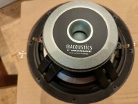
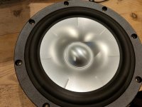
73€ - Dayton Audio SD270A-88 10" (Green)
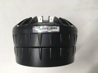
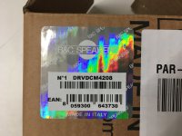
149€ - Dayton Audio DCS305-4 12" (Blue)
109€ - Dayton Audio SD315A-88 12" (Red)

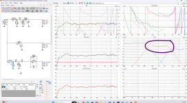
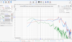
On winIsd, for a ported enclosure :

2022-04-14_11h51_17.png


Budgetwise : SD270A-88 but too high above Xmax (at 120W)

So, Budgetwise 2 : SD315A-88 but too higher than Xmax (at 120W)

Last choice : DCS305-4 almost down to where I want, spl, group delay, cone excursion, rear port air velocity OK !
--> 120L box, tuned at 23Hz
--> 500x40 mm port (lenght 825.8 mm) BUT the 1st port resonance : 208Hz ; is not an octave above my desired LP filter.

And then, I'm completely lost on the crossover design, I made a 4th order, but it seems that it will cost so much...

2022-04-14_12h12_46.png


So here are my questions :

- Any Ideas of other greater drivers ?

- Does a subwoofer need to go as high as 250Hz ?

  • How to define the 1st port resonance ? (I read that this should be 1 ocatve higher than the LP filter)
  • How to design better to meet all the requirements ? (1st port resonance, cone excursion, group delay, ...)

- Could you help me design a low budget crossover ? (I don't have much experience, I'm learning everything to achieve it)

My WinIsd files are also attached.

It might be too difficult to meet all these goals but I'm willing to get as close as I can !

Thank you very much for any answer !

Olamm
Projects by fanatics, for fanatics
Get answers and advice for everyone wanting to learn the art of audio.
Join the Community
507,744
Members
7,886,471
Messages

Filter

Forum Statistics

Threads
406,154
Messages
7,886,471
Members
507,744
Latest member
HMac60