DATS v3.16 crashes on start-up

Hi! I just wanted to check if anyone else has experienced this: the DATS software (v3.16) crashes on start-up. It renders the user interface partly for a few seconds, then just disappears. I just bought my DATS V3 rig, so this is not was I was hoping for 🙁

Notes:
- I've rebooted my computer after installing it.
- I've set the audio device settings to stereo 44.1/16.
- I've tried different USB ports.
- The blue light is on the hardware.
- There's nothing connected to the alligator clips.

Anyone got pointers on what I could try? Does it need any runtime frameworks like a spesific version of .NET or something?

New active 3-Way, Hypex and SB

I just completed a new active 3 way system. I used a pair of Hypex Fusion FA253 amps.

Woofers are SBA SB34NRX75-6, in a 70 liter sealed box. The ideal sealed box for this woofer is about 110 liters, so I used a Linkwitz transform to adjust the response. boost starts at 38 Hz, and by 26 Hz I have 6 db of boost. The crossover to the mid is currently 200 Hz LR4.

The mids are SBA SB17CAC35-4, an aluminum/ceramic 6 inch driver. The box is 10 liters sealed. The cabinets have 1.5 inch roundover on the sides, and a 30 / 60 degree dual bevel along the top.

The tweeters are SBA SB26CDC-C000-4, an aluminum/ceramic dome. Crossover from the mid is 2 kHz LR4.

The Hypex DSP features are powerful, and I was able to equalize all the drivers flat through the passband and stopband. I applied digital delay to the mid and tweeter to bring all the drivers into the same plane as the woofer. The Hypex amp is mounted in the speaker stand.

I am not done fine tuning the filters, but I am going to listen to them for a few weeks before I make any further adjustments. They sound pretty amazing right now.

Thanks for everyone who conversed with me over the last 7 months. I learned a lot, and this project would not have been successful without the DiyAudio community.

Attachments

  • L20200414_093034.jpg
    L20200414_093034.jpg
    583.5 KB · Views: 3,059
  • L20200414_093216.jpg
    L20200414_093216.jpg
    513.6 KB · Views: 2,926
  • L20200414_093058.jpg
    L20200414_093058.jpg
    507.1 KB · Views: 2,811
  • L20200414_093511.jpg
    L20200414_093511.jpg
    532.6 KB · Views: 2,857
  • L20200412_162305_HDR.jpg
    L20200412_162305_HDR.jpg
    771 KB · Views: 2,778

Only 100 hours? (and click-bait — $650k loudspeaker)

STRP_1224_Oneiros_011.jpg


https://www.stereophile.com/content/inside-oneiros-audio-speaker-launch-living-colour

They boast that there is 100 hours of CAD work to do this design. I do lots of CAD work drawing loudspeakers. 100 hours is a joke … some drawing sets i do take a fifth that much, that is with flat sheets. As Chrisb says, curves cost money. 1000 hrs is more realistic.

dave

Compressor schematic and routing on EDA (need help)

Hello everyone !
I was looking for a simple audio compressor to pair with a microphone for live use, dedicated to the microphone. What do you think of this one? It has many interesting settings: input gain, ratio, threshold, make-up gain, THD set
I want to make pcb copies of this audio compressor. I tried to reproduced the schematic on EDA, this is the original link : Compresseur audio Sonelec 002 (for private use)

I have several routing attempts, I don't know which one is the best in the end because it's the first time I've tried this. I have a user constraint for the design of this PCB : place all the potentiometers on the front of the chassis, in direct soldering without additional wires. This is why I start with a PCB border of approximately 130x90mm. I only applied one beginner's rule... keep direct connections between components as close as possible.
what do you think about the schematics and routing suggestions of EDA ? I used automatic routing. With 2 layers there are 6 vias, with 4 layers there are 3 vias. No error messages, EDA indicates when the tracks are too close to each other...

Photo n°1: original schematic (x2 mono with link option). SW1 is a switch to connect two PCB together.

electronique_compresseur_audio_002.gif


Photo n°2: my reproduction on EDA (x1 mono). what is not clear to me is : what happens to 18v and 18va written on the original diagram, at the time of automatic routing ? In my version, power is named "ALIM"! after routing (without error), the two tracks 18v and 18va of the original schematic disappear, can you explain to me why?
schemùatic.PNG


Photo n°3: 2-layers routing (ALIM = POWER !)
2 layers.PNG


Photo n°4: 4 layers routing (ALIM = POWER!)

4 layers 1.PNG


Photo n°5 : 4-layers routing n°2

4 layers 2.PNG

Large Wood Horn Design for B&C DCX464 in 3 way active speaker

Hello all -

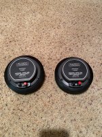
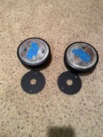
I've been lurking here for a long time with some moderate contributions, and have been scouring the forums trying to understand a direction for a custom speaker I'm building around the B&C DCX464. Really, it's being designed around aesthetics - I have always loved the look of big wood horns ala Oswalds Mill Audio and A for Ara. I know the two aforementioned companies build luxury items for a price point that is out of reach for almost everyone, with a sound quality that can likely be achieved for much lower; however, I'm an architect and one of my fatal flaws is that I like how things look as much as how they perform.

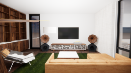
The design for this speaker thus started with a visual idea more than an acoustical one - I wanted a big (24" +/-) round wood horn set atop a bass cabinet down below. In looking at several options, it appeared to me the best way to achieve this was to 1. keep the crossover point relatively low (to achieve more flexibility in driver-to-driver spacing) and try to play as much of the frequency range from the horn to keep it as point-source as possible. I saw the DCX464 reviewed relatively favorably on Joseph Crowe's site, and given its broad range and low crossover possibilities, I thought that driver might be the ticket.

I use a program called "Rhino" for work, almost 8 hours a day, and have been for nearly 15 years - so there is nothing outside my capability for modeling. I am also an expert in a parametric program called "grasshopper," so I've been able to translate some of the more complex math involved in various designs into parametric models that allow for extremely fast and quick experimentation (I have built a pretty comprehensive model that allows me to iterate through tractrix horn constructs with petals). I have a 3D printer and a CNC and have been building furniture for 25 years, so there are few things outside my fabrication abilities.

Where I quickly fall apart is trying to determine what exactly the geometry of the actual horn/waveguide should be. I have read a lot of different opinions, but realistically what I'm looking for is good sound that works on a relatively wide dispersion - it doesn't have to be the same EVERYWHERE, but I'd like to avoid a full-range pin-point sweet spot if at all possible.

I've been looking at a lot of other precedents for contemporary horn drivers, including the Oblate Spheroid waveguide, Joseph Crowes ES290 horn, the Advance Transition Horn EXAR, and tractrix horns in order to try to find some commonality between all of them in the design. I have drawn all these in CAD and plotted them for comparison.

I'm also curious about the "pleats" in the X-Shape waveguide (mostly because I could fabricate and think it looks cool) - but don't really understand what it is doing acoustically. https://audiohorn.net/x-shape-horn/

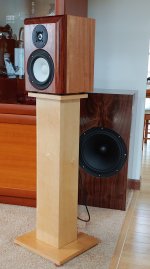
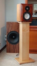
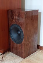
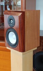
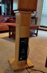
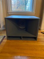
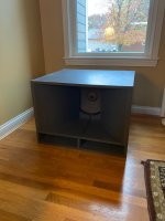
Attached is the curve plot comparison, as well as a couple of early renderings of what I think the cabinet would generally look like. I was looking at the Faital Pro FR400 for the lower end. I'd be doing an active system with maybe a passive crossover for the compression driver. I'm looking for opinions - about horn design, general thoughts on the speaker design, etc. Thank you!

Attachments

  • Closeup.png
    Closeup.png
    2.4 MB · Views: 274
  • From Bar.png
    From Bar.png
    2.5 MB · Views: 114
  • Horn Design Comparison Chart.jpg
    Horn Design Comparison Chart.jpg
    49.7 KB · Views: 123

ISO Resistor (out of stock everywhere)

I'm in need of a replacement for this resistor in my MEP803A generator. It's designated "LED resistor" on the schematic and is in series with the AC interrupter. The resistor failed last week and I've got a couple of alligators and a couple of cement resistors temporarily jumped in, but I would like to find the correct part. All of the electronics supply houses have them as non-stocked items, but if I want to order 180 pieces, they're happy to order them. LOL

Here's the spec and a photo.

HLM-10-10Z-16
1.3K Ω 5% 10W


1733358713830.png

Hifonics BRX3016.1D PS mosfet Identify

I’ve received this amp for repair but previous tech had mixed parts inside, I’ve come to think that the 1405’s are the original but none shown here are available to me, can I go with 064N if yes what’s the best gate resistor to use currently there are 39ohms but I don’t have that resistor currently, any thoughts?
image.jpg

Attachments

  • image.jpg
    image.jpg
    1.1 MB · Views: 37

NAD 314 - which capacitors should I replace

Hi

I have a Nad 314 with Mordaunt Short MS10i speakers, Cambridge Audio CD4 and Dacmagic2, bought in the late 90s. Over the years the bass became more loose and rumbling, and recently one of the woofers went open circuit, so I purchased some Wharfedale 12.1 as a replacement. I also replaced all the power capacitors in the amp.

The wharfedales are bright and sound good with vocals, but the bass completely overpowers any bassy tracks, especially electronica.

A discussion with Richer Sounds points me to the amp rather than the speakers which was my thinking too.

So, after reading for a few days, I'm trying to decide if replacing all the capacitors in the NAD will fix the issue - or perhaps just replacing capacitors which affect the bass? 3 of the power capacitors were around 30-50% of their rated value.

Thanks in advance for any advice or comments.

Ray

Autotek MX1300 Mean Machine rebuilt

Did a power supply rebuilt on one of this amp many years ago, now the customer wants to decommission one to restore the other, board was burnt to cinder back then so a lot of jumper connection was mandated. Now all I’m to do with the better looking one is take the parts from the bad looking out of chassis board and repair the one that he brings in the chassis. May the good Lord be with this restoration. 🙏

Attachments

  • IMG_1263.jpeg
    IMG_1263.jpeg
    1.2 MB · Views: 38
  • IMG_1264.jpeg
    IMG_1264.jpeg
    1.1 MB · Views: 41
  • IMG_1265.jpeg
    IMG_1265.jpeg
    821.8 KB · Views: 36
  • IMG_1266.jpeg
    IMG_1266.jpeg
    1.1 MB · Views: 39

MTX 1501D repair help

Hello everyone. I have a mtx 1501d that is in protect mode. I am a seasoned tech and work on a ton of home audio gear but am very new to auto amplifiers. I would like to get this thing up and running. I cant find a service manual for this amplifier and am hoping I can use this amp to get me more familiar with auto amplifiers. I popped the top and found four HUF75339P that have been destroyed. Looking at the speaker terminal strips it appears someone was wiring subs up to this amp while it was on and shorted one of the wires to the case ( arc marks on the case). Nothing else in the amp looks visually bad. I ohmed out all the ouput transistors and they dont appear to be shorted. Il post a couple pics. Are these fets still in production or are you guys using modern replacements? I work on a ton of vintage amplifiers and allmost allways need modern replacement. Anyhow if you guys can kind of give me some tips or help with this that would be awsome. I will post a couple pics and look forward to hearing from you guys.

Attachments

  • 17309996134056616530599889119629.jpg
    17309996134056616530599889119629.jpg
    724.4 KB · Views: 144
  • 17309996269046262807843210092515.jpg
    17309996269046262807843210092515.jpg
    492.3 KB · Views: 101
  • 17309996367653366478240884750777.jpg
    17309996367653366478240884750777.jpg
    361.9 KB · Views: 98

Volume Pot options for amplifiers "Dual Gang"

1727265076539.jpg
1727265076543.jpg


Hello, I have develop this pcb for volume control,I do have severall modules and parts from National Semicondutor
but this have been developed mainly
for the ones with LM3875 which you can check here:
https://www.ebay.de/itm/325923530044
Here I am using a RK27 ALPS dual gang pot,but I am looking for a better price point using other pot, and

I would like to know what forum users do recomend?

Hello from Florida

Good morning everyone, making my obligatory introduction post. I've been a big music nerd for my whole life but never really had the budget for any high end gear so have mostly stuck with midrange headphones or vintage scores from craigslist etc. Just bought a house with the SO and working on furnishing so I'm thinking its a good time to integrate a good audio solution. Current daily driver is a 1968 HH Scott 2550-W "Scottie." Funky little solid state bookshelf receiver with matching enclosures that I scored for $50 nearly 10 years ago. The drivers were trashed when I bought it so I swapped them for some bose 6.5" papercones from the parcel shelf of an early 2000's mazda millenia. Complete swag on my part but ended up being a nice fit sonically. This little guy is great (likely needs some recapping) for an average sized bedroom but runs out of my steam in my open plan dining room/kitchen.

My current plan is to grab a single ended EL84 amplifier (some china junk but very workable with some simple mods from what I have seen) and do a full range build like pencils or something similar. I'm a little stuck on driver selection and that's why I'm here.

JVC Mini System with CD tracking fault

@Mooly, Hello, I would like to ask you a question about a JVC mini system, the laser pickup is a SOH-AAN -04H, at least that's what the label says.It's strange what I found, at least for me, I notice that it takes a lot of work to read the TOC, but once it does, it doesn't start on track 1, I order it to go to 2, 3, etc. and it does it without problems, it reads perfectly and if I send it to number 1, it executes perfectly, if I change the disk, the process repeats itself. I thought it might be dirty in the pickup position sensor, but here's the thing, I attached some photos, the sled doesn't activate the switch, there is no physical contact between them and it seems like there never was, it doesn't seem like any part is missing or broken. Is this possible? According to the service manual, the switch signal carries information to the MCU.

Attachments

  • 20241213_162224.jpg
    20241213_162224.jpg
    207.7 KB · Views: 54
  • 20241213_162302.jpg
    20241213_162302.jpg
    262.2 KB · Views: 44
  • 20241213_162310.jpg
    20241213_162310.jpg
    253.1 KB · Views: 49

McIntosh C-28 preamp in question

I have a c-28 solid state preamp using it on my mc-2500, and my mc-7270. I seem to be quite disappointed with the sound quality of it. It just doesn’t sound clean and clear as a MAC should. Even with the bass trim turned down, the musical clarity of the bass + treble tones etc. just isn’t as defined as I thought they would. It just sounds mushy, noisy, boomy and tasteless. I own several other MAC pieces, but I’d just like to know if this particular preamp is a reputable pre, or should I just get rid of it and try something else in its place?.
Anyone who’s tried this pre please let me know. Maybe one of the other MAC would fare best. Please help me. Thanks y’all!

Help repairing old Philips speakers

1. Is this tear repairable? If so how?
2. Why does the cone look wet around the edges
3. How do i clean the dirt off the speaker.
4. Are those tweeters even real?
5. The tweeters seem to be hooked up directly in parallel with the speaker. Is this okay or the resistor i found goes in somewhere.

Any help will be highly appreciated

Attachments

  • 1000049549.jpg
    1000049549.jpg
    532.8 KB · Views: 118
  • 1000049551.jpg
    1000049551.jpg
    640.9 KB · Views: 109
  • 1000049553.jpg
    1000049553.jpg
    538.1 KB · Views: 155
  • 1000049555.jpg
    1000049555.jpg
    544.8 KB · Views: 114
  • 1000049556.jpg
    1000049556.jpg
    700.8 KB · Views: 95

Best/Least expensive way to use 2 raw drivers and woofer

“A Champaign lifestyle on a beer budget” may not be possible in general, but I believe is somewhat attainable in audio. I would like to replace my Yamaha receiver – CRX TS10 – with something (hopefully) better. My budget said class D. But I read a lot about “power”, but nothing about “musical.” So I searched for a good used A/B. The Nakamichi SR 2A (30 RMS into 8 ohms; 45 max; 55 max into 4 ohms) designed by Nelson Pass and received some very good reviews (https://bargainaudioblog.com/2018/05/13/nakamichi-sr-2a-stereo-receiver/ ). This has set me back $127.00, but was in my budget. Now for some speakers. Therein lies the rub (Shakespeare?).

I checked all kinds of reviews and eBay listings. I could find nothing suitable for less than about $400.00. I have in the past made a some speakers from the Madisound website for my tube amp – long since gone. So why not build again?

I viewed a number of “Kirby meets audio” videos. He recommended 2 Dayton Audio PS 95-8 3.5” full range speakers (85.56 db 2.83V/1m; 10 watts) and a Dayton Audio DCS 165-4 ( 87.4 db 2.83V/1m; 100 watts). This, plus about $70 in hardware, 14 gauge wire, fiber-fill (etc.) will set me back $170. This is on my Parts Express order, but I have not yet pulled the plug.

As of now, I have about $300 potentially committed – not a lot for most people, but a fair amount for me. But what price audio nirvana? (yeah, sure…)

The reason for all the specs is because I built a number of projects, I still do not understand electronics very well. If the instructions say “solder wire from point A to point B,” I can do it. But don’t ask me to explain why.

Now comes the question(s): how to I set up these (or other) speakers to best advantage (want frequency response down to about 40 hz):
  1. Separate enclosures for each (wood cost s/b cheap – small boxes). Hook up the PS 95’s to channel A; sub-woofer to L or R of channel B. Play both channel simultaneously and use base tone control to adjust bass SPL. I have no idea if this will work – 8 ohms vs 4 ohms impedance? Will my 30 watt amplifier be able to provide enough juice? Etc. No extra costs.​
  2. Separate enclosures for each but use a crossover in one, output to 10 ft wire to sub-woofer. But will this work? Impedance mismatch on speakers a problem? Etc. Extra costs: some hardware and crossover components​
  3. Add a Dayton Audio DTA-2.1BT2 100W 2.1 Class D Bluetooth Amp for $85.00. Or the Dayton Audio SPA100-D 100 Watt Class-D Subwoofer Plate Amplifier for $90.00. Or the Dayton Audio work if no RCA low out from my amp? The first one was recommended by “Kirby meets audio,” so it must work somehow, but these is no Bluetooth in my system. and no low frequency out. This second option seemed to work per a previous thread - see https://www.diyaudio.com/community/threads/connecting-a-single-passive-sub-to-stereo-amp.371607/
  4. Use 2 speaker/cabinet design. Keep the PS 95’s(?) and use different woofers(?). Net costs: unknown – may be less, probably more.​
Well, there you have my potential stereo upgrade options. Are some of these completely not doable? Are there better options? I am open. My expertise is limited. As in I have never designed a crossover network.

Music preference: classical, 50’s jazz, vocals, some 70’s rock.

May thanks in advance for any comments/suggestions.

Small Acoustic Research woofers 200046-0

I had these small (looks like Acoustic Research) reconed. Trying to find any information on those.
Heard they might be used in a small 3 way ARms1? Any info? Anyone needs them?

Attachments

  • PXL_20241201_215345478.jpg
    PXL_20241201_215345478.jpg
    520.7 KB · Views: 26
  • PXL_20241201_215349681.jpg
    PXL_20241201_215349681.jpg
    502.6 KB · Views: 27
  • PXL_20241201_215400507.jpg
    PXL_20241201_215400507.jpg
    545.1 KB · Views: 24
  • PXL_20241201_215608917.jpg
    PXL_20241201_215608917.jpg
    577.5 KB · Views: 30
  • PXL_20241201_215616166.jpg
    PXL_20241201_215616166.jpg
    483.7 KB · Views: 23
  • PXL_20241201_215819101.jpg
    PXL_20241201_215819101.jpg
    367.1 KB · Views: 35
  • PXL_20241201_215825337.jpg
    PXL_20241201_215825337.jpg
    423.8 KB · Views: 27

Hifonics BRX2016.1D no sound

im new to amp repair as far as getting into reading component values and undersanding how it actually works.. i have an cheap oscope but not sure how to really use it..

so i have a hifonics brutus 2016.1d that powers up but has no sound except a loud pop when i turn off the power.. thinking about it this it might be cuz im just cutting the power supply and not turning off the remote first.. ill try that next time..

1 side of output fets read 77.5 volts on the drain and the other side reads 77.5 volts on the gate and source is that normal?

i found a chip on the driverboard was burnt so i ordered a new one based on what i found online was chip lm211 and it was a bit larger than the one on the board.. i put it on anyway.. i know not the right move im sure but what should i be checking and whats the correct part to order?

Running BMS 5530 / 4550 down to 600 Hz

Has anyone tried running one of these drivers down to 600 Hz in an appropriately sized horn with a steep electronic filter?
BMS themselves actually rate it from 500-20 000 Hz.

Seems to handle even 110 db at 600 Hz on the Dayton H812 so I can't imagine it being an issue in a domestic setting:

https://www.justdiyit.com/grand-comparatif-de-compressions-1-pouce/5/

Overlay-H3-110db-bis.jpg


In fact, all of the ones in the above test seems to be fine (with the odd exception of the ND350)

An EF184 + 25L6 2.2W guitar tube amp

HB-1 Amp - An EF184 + 25L6 2.2W guitar tube amp

I forgot that I had posted an old version of this scheme here, in the The Hundred-Buck Amp Challenge thread, until an user of a Brazilian forum reminded me of it today. Coincidentally, the first name of this amp was 100Buck Amp.
It is a 2.2W amp, EF184 + 25L6 tubes, with a really good sound. The power transformer is a ordinary 30+30V 30VA. The output transformer is a 1.7K - 8 ohms SE .
Here you can find a review of this amp (in portuguese): Crow | The 100 Buck Amp | REVIEW por Zarbinatti - YouTube
You can build it for less than $100...


And here the last scheme:

101Esquema_Novo_3.6_Fonte.jpg


*If anyone wants, I can update the PTP layout of this amp and post it here.
  • Like
Reactions: djgibson51

For Sale Twister Pear modules

Years ago I bought a set of TPA kits, then forgot then in a closet. Just found them and I don't need them any more.
Seems like they are soldered by a beginner, not me. On some of the boards there are parts missing and cut or shorted, refer to pictures. Some are unsoldered kits.
I will prefer to sell them all at once. Price for the complete lot is 70€ + shipping.
See photos for details.
-2x Counterpoint
-2x Sidecar
-IVY 2.0
-IVY III sold
-S/PDIF module CS8416
-4-channel S/PDIF level converter
-CMP1 v1. 0
-OTTO II

Attachments

  • IMG_20241125_191156.jpg
    IMG_20241125_191156.jpg
    750.5 KB · Views: 106
  • IMG_20241125_191207.jpg
    IMG_20241125_191207.jpg
    574.6 KB · Views: 101
  • IMG_20241125_191214.jpg
    IMG_20241125_191214.jpg
    389.1 KB · Views: 81
  • IMG_20241125_191220.jpg
    IMG_20241125_191220.jpg
    438 KB · Views: 81
  • IMG_20241125_191222.jpg
    IMG_20241125_191222.jpg
    380.2 KB · Views: 77
  • IMG_20241125_191226.jpg
    IMG_20241125_191226.jpg
    402.2 KB · Views: 82
  • IMG_20241125_191230.jpg
    IMG_20241125_191230.jpg
    713.2 KB · Views: 86
  • IMG_20241125_191240.jpg
    IMG_20241125_191240.jpg
    747 KB · Views: 81
  • IMG_20241125_191247.jpg
    IMG_20241125_191247.jpg
    705.7 KB · Views: 83
  • IMG_20241125_191251.jpg
    IMG_20241125_191251.jpg
    694 KB · Views: 100

SMPS or Transformer?

Hi everyone! This is my first thread on this forum.

I'm planning to build an amplifier to drive a pair of 8-ohm, 15-watt speakers I have. They're reasonably priced but capable of delivering decent sound quality.

I've decided to use a couple of LM1875T-based amplifier modules for the power amp section. These modules require a dual-rail power supply. I'm sure many of you are already familiar with them, so I won't go into further detail about the modules.

H5b15adb5fc69403c9dbe615feab95239N.jpg_960x960.jpg


I'm considering two options to power them: either connecting two 24V SMPS modules in the following configuration,

Untitled.jpg


or using a toroidal transformer with a full-bridge rectifier and some smoothing capacitors

(I'll check if they're completely isolated from the mains supply before connecting the pair in this manner, to avoid any possible short circuits )

I've read in several places that SMPS units tend to introduce harmonics into the power line and generally deliver lower-quality power compared to toroidal transformers. Is there any truth to this statement? I know these amplifier modules are not of premium quality, but I'm eager to improve them in every way possible. I’d greatly appreciate your valuable advice.

Additionally, how much current are we likely to deal with here? The modules are rated for a 20W output each, but I understand they will waste a considerable amount of energy as heat

For Sale H9KPXG Hicoco European version

I've got 3 of these boards for sale made by JLC pcb, it's Hicocos version of the H9KPXG soft start, which is described in this post 545 here https://www.diyaudio.com/community/...soft-start-h9kpxg.354971/page-28#post-6947574

The Pcbs are 1.6mm thickness with 1oz copper and HASL finish

Just want my costs covering £18 with UK postage included

Attachments

  • 20241216_140733.jpg
    20241216_140733.jpg
    432.8 KB · Views: 55

Proper crossover component selection, VirtuixCAD power dissipation curves

Hi there,
Driver is 5,5 C 1,5 CP 8+8Ω coax.
https://sica.it/wp-content/uploads/2023/12/Z002810.pdf
According to specification it is 120W AES and 240W Continuous Program Power speaker combo. AES is measured with 6dB crest factor as per manufacturer info.

Crossover:
Sheshtas var7 XO-schema-7.png


If I do use VirtuixCAD Power dissipation tool with 240W on 8Ohm with "Flat" settings, I get so ridiculous results, that there seem to be no such resistors in the market. 25-40W of power dissipation for single component seems too much for a 5 inch woofer and 1 inch dome tweeter. But If I use "M-noise" setting - everything seems the other way around - too little power going through components.

Now the speaker in on the active crossover and powered by the Class D TPA3250 ~40W/8Ohm per channel amp, so 40W for woofer and 40W for tweeter (24V 4A power supply). The exact numbers are not important and probably not correct anyway, but lets assume it has at least 30W per channel.

So, the thing is - I cannot fully crank volume signal, it seems that this small amp can melt this speaker on the spot(~-2dB attenuation on PC global, with 100% volume, Presonus 26c as soundcard/preamp, max gain on mechanical gain knob). It is not 240W or even 120W driver. NO WAY!

The question is: which settings should I use for simulations on VirtuixCAD?
On the normal listening conditions I would use 5W resistors and call it a day, but I now I have doubts...
R4 is ~26W on 900Hz, R5 is ~41W on 20kHz(!). My guts say that 20W for R4 and the same 20W for R5 is more than enough. Right?

Screenshots attached
power.png

current.png

voltage.png

Newbie on board!

Hi everyone!

I’ve been lurking around this forum for quite some time and finally decided to register.

There’s not much to share about myself in terms of experience—I'm a rookie in the audio scene—but I’m eager to learn and excited to dive deeper into this fascinating world.

I also have a small project coming up. It’s not an advanced one, but it’s something to help me get started and explore a hobby I’ve been interested in since I was a kid.

From starting out with a Panasonic portable cassette player, I’ve slowly been exploring and experimenting with audio equipment. While I still consider myself a beginner I’ve owned and experienced a variety of Hi-Fi gear, though nothing audiophile-grade. I’m not really into expensive or exotic equipment—what excites me more is finding affordable, easy-to-maintain gear that delivers a quality musical experience.

Looking forward to learning from all of you and contributing where I can!

Cheers!

volume controller scheme for computer output

I need a simple diagram of a volume controller, using a double sliding potentiometer. I need to connect the headphone output of a computer to its input. It is important that the output is balanced, to be connected to 2 active speakers with XLR input.
I don't know if it is possible to make this circuit in passive mode. This would be perfect.

A question for the MEH enthusiast and builders?

So let’s consider another option…..say a 2” mid compression driver that can load down to 500hz and play up to 8.5k or so……not a hard task. But what to do about the top octaves? Has anyone considered a surrounding multiple tweeter approach?…….something like say the Dayton ND20fb?……4 units flush mounted in the throat very close to the mid exit? 4 of these little guys in series parallel should be a good efficiency match to a mid compression driver.

Bass quality vs step response

While browsing loudspeakerdatabase I noticed bass drivers have wildly different step response. At 60hz most long and medium throw drivers don't even remotely track the input signal.
1000003548.jpg

The cheap Goldwood with only 2mm xmax does a lot better

1000003547.jpg


The only driver I could find doing slightly better than the Goldwood is the insane 31.5" Fostex
1000003549.jpg


If we disregard the practicality of it, would 4 Goldwood drivers sound better than one driver with 4x the xmax and 4x the price in the low bass region (30-120hz)?

How important is step response and which driver parameters are important for good step response?

Cascoded fully differential headphone amp

Hello Everyone!

You might remember that about half a year ago I built a hybrid opamp MOSFET fully symmetrical headphone amp that I call M4:
https://www.diyaudio.com/community/...ial-hybrid-opamp-mosfet-headphone-amp.409976/

It's working quite well although I cannot say anything about noise figures or THD+N.
This amp was always meant to be a stepping stone up to the big leagues of something high-end. This is where I am seeking guidance from the community. These are my ideas for future upgrades:

- Raise the PSU voltage to +-15V, upgrade the opamp to OPA1633 and cascode the MOSFETs like in the AMB Beta22 amp with the same topology except for driving the MOSFETs. That would be identical to the current version (2 JFET CCS bias of the OPAMP through the + and - rails). I believe that this setup would provide optimal noise (OPAMP VAS with -132dB noise) and THD+N (cascoded output stage)

- Use the fully discreet design of the beta24 (https://www.amb.org/audio/beta24/) with the output stage of the beta22 (https://www.amb.org/audio/beta22/) with a single regulated PSU (sigma 22). This could be the ultimate headphone amp if done right. The problem with it is that it needs matched components. I could source the input JFETs from diyaudiostore for about 100USD (quite a bit for 8 JFETs but still better than no JFETs), but I am having trouble in locating a good source for the BC550 BC560 BJTs. Especially, that I need 24 of each of them. I could get them through ebay (questionable) or dig through the entire internet. I could also use some better complementary BJT pairs based on the Horowitz book, although, I couldn't find obvious ones to use. I could also use SMD JFETs and BJTs but then I would need to redesign the circuit and the PCB completely.

Here is what I have for this amp:

Schematic:
schematic1.png
PCB:
onboard_heatsink.png

Do you see any potential upgrades in either of these projects? Which one would you recommend pursuing (if any)?

Happy Sunday!
Cheers!
  • Like
Reactions: Nisbeth

  • Locked
Audiophoolery

Found this 2005 article from Skeptic magazine:

https://ethanwiner.com/audiophoolery.html
You might think that a science-based field like audio engineering would be immune to the kind of magical thinking we skeptics see in other fields. Unfortunately, you would be wrong. In my 35 years as a professional audio engineer and musician, I've seen some of the most outrageous pseudo-science sold to consumers, and even to other audio pros who should know better. Not unlike claims for alternative medicine, nonsense is shrouded in scientific-sounding jargon to confuse the uneducated. Or a sales pitch will cite science that is legitimate but irrelevant, such as the molecular structure of a wire without considering whether an affect is actually audible. The result is endless arguments among audiophiles over basic scientific principles that have been fully understood for fifty years or longer.
As a consumerist, it galls me to see people pay thousands of dollars for fancy looking wire that's no better than heavy lamp cord they can buy at any hardware store. Or magic isolation pads and little discs made from exotic hardwood that purport to "improve clarity and reduce listening fatigue," among other surprising claims. The number of scams based on ignorance of basic audio science grows every day. Surely some of these vendors know they're selling snake oil, but I'm certain that just as many believe their own hype. I'd respect these people more if I thought they knew they were conning people!

Few of us have unlimited budgets and must spend what funds we have wisely. Therefore, the purpose of this article is to help you distinguish truth from fiction, so you can determine what is and is not worthwhile. Experience has shown that it's futile to claim I know what someone else can or cannot hear. Therefore, I will relate only those things that matter to my experienced ears, and explain what makes sense from the perspective of science and logic. You don't need a college degree to understand the explanations that follow, though I'll assume you've played with a stereo receiver and CD player or cassette deck a few times. I'll begin by defining the four basic audio parameters. Then when I describe some common audiophile scams later on, you'll understand why they are scams.

Treating a speaker as a resistor, a capacitor, or an inductor

Attached is a LP section of either a 2.5 ways or a 3.5 ways speaker. To calculate for L3, I’m curious whether the speaker W1 could be considered as a capacitor, so the calculation can follow standard third-order formula.

Or are there any means to calculate L3 except using simulation softwares, i.e., VituixCAD, REW, etc.? (I can use them but just curious if there’s an alternative method, even hand calculation, available.)

IMG_0216.jpeg

  • Locked
The £25,000 preamp that went wrong - Tom Evans Mastergroove

I'm watching this guy on YouTube that repairs all kinds of audio stuff, and came across this:

Login to view embedded media
I'll let the video speak for itself, but I must say I'm shocked by what shoddy circuits anyone can put together and sell for ridiculous price tags.

  • Locked
Can We Have a Grown-Up Discussion About the Drone Issue

The post that I started last Wednesday on current drone sightings has been shut down by the Moderators. I assume that was done due to the rather silly and somewhat derogatory comments that were being made by some posters.

But this is an important and timely subject. And it is completely nonpolitical. People on all sides of the political spectrum are concerned about it.

So, I would like to continue a serious discussion here and ask that it not be corrupted by unnecessary silly comments.

========================================================

As of now there are still no definitive answers by the government or anyone else.

More sightings continue at a high rate and in new places not previously heard from.

The sheer number of drones that exist in the US alone, almost a million accounted for and probably an equal number unaccounted for, makes this a very serious matter. I don't think people realized until now exactly how many of these drones exist. And more are being manufactured every day.

This issue is not likely to go away soon and seems to be certainly worthy of a respectable discussion here.

How can you split a vented speaker box in two?

I have a broken Sony GTK-XB5 speaker, the electronics are broken and one of its woofers too, my idea is to use a woofer and a fullrange to make a smaller self-powered Bluetooth speaker.

I thought that if I took the volume of the box and split it in half and did the same with the length of the bass reflex tube I would get a box that sounded the same but smaller but trying in WinISD I have seen that this is not the case, and I do not have the thielle-small parameters of the speaker.
I have a 3D printer and a calibrated microphone. My idea was to make a box with half the volume and try different bass reflex measurements until I got the desired response, but I don't know whether to start with the same diameter or a smaller one.

How would you do it?

Help with noise in one channel of headphone amp

Hello,

I have a Rudistor RPX-33MK2 headphone amp which is producing noise in the left channel. The noise comes on a few minutes after the amp is turned on. The channel still works, but the static noise is just there along with whatever is playing. I've recorded a sample of that, which can be heard here - https://app.box.com/s/7htgpg3ieiuytt61qwhsd5ux05i3b0bf

I wanted to ask for some advice on how to go about resolving the issue. I can see the trimpots, maybe need to adjust those but have little idea where I would point my multimeter to..

Any tips are most appreciated, would like to put this dude back in use 🙂.

Thanks,
-Art

PXL_20230713_170910433.jpg
PXL_20230713_170935720.MP.jpg

Attachments

  • PXL_20230713_170935720.MP.jpg
    PXL_20230713_170935720.MP.jpg
    166.3 KB · Views: 184

Help needed with understanding PSUD2

Hello All,

Very much new to understanding this program.

I'm trying to understand how to get loaded B+ measurements at output transformer with using the Vta st70 as a template. Mine is the same power supply section besides transformer to the Dynaco ST70 attached schematic.
transformer is 360VAC @350mA
output transformer is 4.5K
I'm running 6l6gc output tubes and 6ns7's on the driver board.

When loaded With a multimeter its got about 440vac at C1, 430vdc on the plates of 6l6 with 40mA bias and 375vac on the driver board B+ which is correct to the Octal schematic

Attached is a screen shot what i have so far which seems like Ive done something wrong
So, Is the B+ voltage for output transformer read from the V(R1) RMS? C1 voltage isn't 440v

Help is much welcomed 🙂

Wayne

Attachments

  • Screenshot 2024-12-10 101619.png
    Screenshot 2024-12-10 101619.png
    42.8 KB · Views: 86
  • Schematic octal.pdf
    Schematic octal.pdf
    326.6 KB · Views: 48
  • Dynaco_ST70_VTA.jpg
    Dynaco_ST70_VTA.jpg
    82.5 KB · Views: 76

Box Design Brainstorm Idea

I'm planning to build a speaker, but I want to build something different - thinking outside the box (pun intended). I'm planning to build it out of either 12mm or 1/2" birch wood plywood. Maybe you guys have better ideas on construction materials. I drew a rough sketch of what I thought might work good (open side-view attached), but I need you professionals to give me the exact dimensions that would work best - or just tell me if the design just plain won't work.
1730249875191.png

Hello world!

Hi.

Dave here.

I lurked on here to build a headphone amp a long time ago, and have been back lately as life changes a bit.

I just built some of the redux amp camp amps. They came out really nice- using them to drive some speakers in my shop. Not the most powerful but sound alright, and it keeps the neighbors from getting too upset about volumes and my lack of control. 🙂

Main listening is currently a simple system; Bluesound Node as streamer / DAC, Naim Nait XS, with ProAc 2.5 Response out the end, with Naim cables throughout.

I'm thinking about building more because it brings me joy, so I'm now posting and getting started. (And learning is such a great thing.)

So, thanks for such a great forum.

Dave.

Wiring DVC sub to plate amp?

Just have a few questions on wiring sub to amp. And sub enclosure recommendations for home audio. First off I have a Skar EVL-12 DVC 4ohm and a BASH 500 plate amp, I don't know how to correctly wire these . Being a dual voice coil sub I don't want to wire it wrong and damage my amp. And yes I know this is not the best speaker for home audio but it's what I have. Also is a car audio enclosure different than home audio? Finally any recommendations for a box builder program that works with mac.

DIY Leslie/Doppola Speaker Project Inspired by Dürer’s Solid

Hello everyone, 🙂

I’m currently training as a cabinetmaker, and I’m working on a project to build a Leslie/Doppola speaker inspired by Dürer’s Solid (https://en.wikipedia.org/wiki/Polyhedron_of_Dürer). I also plan to design an electric guitar to match this amp. This post focuses primarily on the technical/electronic aspect of the amp (the guitar being a separate project). My goal is to create a Doppler-effect amp for electric guitar.

After some research, I’ve encountered a few dilemmas:

  • Should I go for 1 or 2 speakers in my amp? Would this improve the sound quality?
  • Should I faithfully replicate a Leslie cabinet, or consider a simplified design that might be less expensive and easier to build?
  • What would be the best setup for guitar? Should I be inspired by David Gilmour’s Doppola, or go with a single-speaker configuration and rotating baffle? It seems to me that the Doppola has a less pronounced effect compared to the Leslie cabinet.
  • Where can I find all the parts needed for this project? (My idea is to start with a tube DIY amp kit that I can assemble myself.)
  • Where can I find schematics or plans for similar projects? Or even other specialized forums for this kind of project, perhaps?
I’m a beginner in electronics, but I’m passionate about this subject, and this project seems perfect to start learning. I will surely post updates if the community is interested (about both the amp and the guitar).

For now, I think a simplified version, like the Doppola or a design with a single speaker and rotating baffle, would be the most coherent, although the original Leslie cabinets are legendary… 😍

Thank you in advance for your advice and suggestions. I’m open to any resources or feedback on similar projects!

P.S. I’m French, so I apologize in advance if I make any mistakes in English!

For Sale Altec 816As loaded with 515-8LF woofers

For sale, a pair of Altec 816As loaded with 515-8LF woofers, 8 ohms. Only driven on Sundays - they came out of a church in Ft. Wayne, Indiana. Asking $1,000 net, plus shipping that you must arrange or pick up from the Cincinnati, Ohio area. Please see my ads for Altec items.

Attachments

  • IMG_0892.jpeg
    IMG_0892.jpeg
    769.1 KB · Views: 46
  • IMG_0891.jpeg
    IMG_0891.jpeg
    774.9 KB · Views: 46

Aspiring Speakerbuilder & Designer

Hey DIYAudio!

I've been a long time lurker of the forums for over a year now - I've caught the speaker-bug & it's consumed most of my free time. Dreaming of a big stack of speakers - putting on unique events & connecting people through sound.

I met my wife on the dancefloor at a unique bass music event in Canada - music has always been a core part of our relationship. We talk about how the event we met at is no more - & where would we meet today of we were that age again?

The desire to curate high quality events surrounding connection through art & sound, quality food & non-alcoholic beverage has me seeking the best possible sound I can possibly create.

Im a builder & do everything myself to the highest quality possible. The level of professionalism here has me excited to be a part of this community.

Recently I've assembled a Maslow4 CNC - working out the kinks to be able to consistently & reliably cut cabs & delve into scenograhy is the goal.

The works of Tom Danley & Tony Andrews are inspiring & how they continue to move the sound world forward is incredible.

Located in the Okanagan area, BC Canada. Very keen to bring something good to the sound world.

Look forward to collaborating with the lot of you!

-Scott

GAS PSP2500.2DF. (made by A/D/S)

Hi.
I'm working on this GAS PSP2500.2DF amplifier (made by A/D/S, model APA21700DFB. http://www.adsaudio.cc/webs/carAudio/detail?id=1000111 )
The amplifier always turns on in protection mode.
On first start, a PWM pulse is given in the power supply, which charges the rail capacitors to +/- 50VDC. If you disconnect the remote and reconnect it, the PWM pulse in the power supply does not appear until the rails are discharged. I have checked both channels and they are correct, I have even replaced the 2092 ICs. I have also checked the power supply control board and everything seems to be in order.
Has anyone had a similar problem?I hope I have explained myself well.

WhatsApp Image 2024-12-15 at 13.15.00.jpeg
WhatsApp Image 2024-12-15 at 13.14.35 (1).jpeg
WhatsApp Image 2024-12-15 at 13.14.35.jpeg
Thanks.

Audio Physic Rhea/Terra

Hi.
Anyone got a scematic for this excellent Sub amplifier?
I have No sound, relay do not turn on, No voltage to relay. No DC on output either. All opamps looks ok when tested separately.

Attachments

  • 17323894418291594664878045832334.jpg
    17323894418291594664878045832334.jpg
    388.9 KB · Views: 90
  • 17323894737621841193392212998484.jpg
    17323894737621841193392212998484.jpg
    302.1 KB · Views: 79
  • 17323895012727288727846427637808.jpg
    17323895012727288727846427637808.jpg
    393.8 KB · Views: 84
  • 17323895147512089002321126606702.jpg
    17323895147512089002321126606702.jpg
    501.9 KB · Views: 81

Peerless 830903 (AW-25i), cant find any parameters or info at all

I have 10 of the mentioned driver at home and planning to build enclosures for them for a movie theater system. I can't however find any parameters for them or really any info at all apart from that they have been available in a diy build kit from now bankrupt Finnish audiostore HIFITALO.

I tried contacting the peerless company but got no answer. Does anyone have anymore info on these or a clue how I could get the parameters I need to design and build a enclosure for them
1733925183988.jpeg

Jamo Studio 180, only the mid working

Hi,
I recently got these 3 way tower speakers from my godfather and when I connect It to my amplifier only the middle was working, I've tried it with a Technics SA-EX310. I've tried it also with a Kenwood KRF-A4030 and the issue stayed the same. All I know about these speakers they were used long time ago.

also here all the specs that I could read of the speakers:
  • Long term power: 100w
  • short term power: 170w
  • frequency range: 50hz - 20.000hz
  • impedance: 4 - 8 ohm

I also know about the technics amplifier It can be used with because it supports 8 ohm speakers.
I also heard that these speaker have a poor crossover and It might need a better one. I really don't know how I can replace it by myself and what kind of circuit bord do i need to buy, but the speakers worked before without the crossover change so I don't think It's necessary.
Sorry If the answer is really clear but I only got this far

Adam
Odorheiu-secuiesc

Been at the Concert today…

Gautier Capucon played Shostakowitch's Cello-Concerto N° 1.
We (wife & I) were right in front of him, ~4 m away. Wow.
It reminded me of a concert of the Who (never saw them live though), he kinda wreaked havoc on his instrument, unbelievable.
Near the end, the 2nd string gave up and jumped off the board, but even this didn't stop him. (A cellist from the orchestra wanted to help out and gave his cello and the conductor had to keep it until the end)
Had no time and no occasion to take a picture.
  • Like
Reactions: sser2
Projects by fanatics, for fanatics
Get answers and advice for everyone wanting to learn the art of audio.
Join the Community
507,905
Members
7,893,193
Messages

Filter

Forum Statistics

Threads
406,470
Messages
7,893,193
Members
507,905
Latest member
Oddball72