Shunt Regulation Part 3
Mix and Match
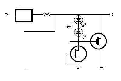
Combining the improvements in both the series and shunt elements, we have an opportunity to create as simple or as complicated a circuit as we need.
Here is a very simple low feedback design. This is just one example of what is possible.
Its virtually mix and match with any of the circuits presented.
Here is the Salas Version 1.1; I consider this to be very good engineering.
The circuit is stable, not sensitive to parts or layout, and not insanely complex.
The original is in the DIYaudio thread simplistic-salas-low-voltage-shunt-regulator, post 501.
http://www.diyaudio.com/forums/power...ml#post1855189
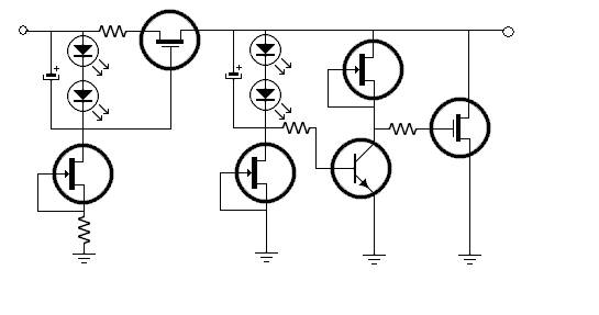
As you can see, you can make this as simple or complicated as you need.
Performance:
Notice that in the circuits I did not give much guidance as to which was better.
That is by design. The circuits are simple enough to try several variations.
Its clear to me that a Better CSS will reject ripple better.
It is clear that a higher feedback shunt will have a lower output Z.
Its also clear that high feedback can threaten high frequency stability.
When feeding a circuit that has a high PSRR, simplicity and stability may be priorities.
For something high gain and low signal, the lower Z may be mandatory.
One size may not fit all.
Additional current through the regulator can improve the regulators stability, ripple margin and device gain.
However, is increases heat, power consumption and may require bigger, more expensive, less ideal parts.
There are other factors. The current through the shunt should be greater than the maximum the load could draw.
Also, for the FET example, the FETs have more Gm with higher current. So a practical shunt runs with extra current.
Remote sensing is required if the regulator needs to be physically separated and the desired output Z is close to the Z of the wire.
Combining the improvements in both the series and shunt elements, we have an opportunity to create as simple or as complicated a circuit as we need.
Here is a very simple low feedback design. This is just one example of what is possible.
Its virtually mix and match with any of the circuits presented.
Here is the Salas Version 1.1; I consider this to be very good engineering.
The circuit is stable, not sensitive to parts or layout, and not insanely complex.
The original is in the DIYaudio thread simplistic-salas-low-voltage-shunt-regulator, post 501.
http://www.diyaudio.com/forums/power...ml#post1855189
As you can see, you can make this as simple or complicated as you need.
Performance:
Notice that in the circuits I did not give much guidance as to which was better.
That is by design. The circuits are simple enough to try several variations.
Its clear to me that a Better CSS will reject ripple better.
It is clear that a higher feedback shunt will have a lower output Z.
Its also clear that high feedback can threaten high frequency stability.
When feeding a circuit that has a high PSRR, simplicity and stability may be priorities.
For something high gain and low signal, the lower Z may be mandatory.
One size may not fit all.
Additional current through the regulator can improve the regulators stability, ripple margin and device gain.
However, is increases heat, power consumption and may require bigger, more expensive, less ideal parts.
There are other factors. The current through the shunt should be greater than the maximum the load could draw.
Also, for the FET example, the FETs have more Gm with higher current. So a practical shunt runs with extra current.
Remote sensing is required if the regulator needs to be physically separated and the desired output Z is close to the Z of the wire.

This page has been seen 7,237 times.
-
-
Created by onLast updated by on
-