well, yes and no.step can't provide parametric adjustability - which is key to have a useful model that can be adjusted following the excel sheet!
On itself no, but there are plenty of programs out there that can convert STEP fine to parametric by adding rules and constraints.
FreeCAD I have as well as Ondselstep can't provide parametric adjustability - which is key to have a useful model that can be adjusted following the excel sheet!
But I could provide a collection of different printable models in stl, 3mf or step format.
I will also try to model a parametric port in freecad.
I am still working on whether the strouhal number limit of 1 is really useful for high quality music reproduction or if it should stay even higher.
I will wait until you settle on a figure before implementing anything further in Hornresp. Would 1.5 be a reasonable compromise perhaps?
Possible to have step file for testing?
I'll let @augerpro decide whether he wants to upload a step file of his port model!

In the meantime here are my models for a NFR=0,5 port.
The freecad model is parametric and can be adjusted as required.
Please note that mounting holes are not (yet) connected to the port exterior diameter/radius, so the respective circle radius in the sketch eventually needs to be adjusted, in case of port diameter adjustment.
The step and stl models (and the as-is-freecad model) have the following parameters:
actual length= 120 mm
effective exterior diameter = 80 mm (defined as radius = 40 mm)
flange width = 25 mm
thus, total exterior flange diameter = (40+25)*2 = 130 mm
flange thickness = 4 mm
port wall thickness = 3 mm
one important hint: the interior port surface should be as smooth as possible (mainly in the central are).
so if the port is to narrow to be smoothed by hand you might eventually want to print two halves for better access to the interior surfaces.
I'll post some pictures of my workflow.
Have fun!
FreeCAD NFR=0,5 port example including STL and STEP
In the meantime here are my models for a NFR=0,5 port.
The freecad model is parametric and can be adjusted as required.
Please note that mounting holes are not (yet) connected to the port exterior diameter/radius, so the respective circle radius in the sketch eventually needs to be adjusted, in case of port diameter adjustment.
The step and stl models (and the as-is-freecad model) have the following parameters:
actual length= 120 mm
effective exterior diameter = 80 mm (defined as radius = 40 mm)
flange width = 25 mm
thus, total exterior flange diameter = (40+25)*2 = 130 mm
flange thickness = 4 mm
port wall thickness = 3 mm
one important hint: the interior port surface should be as smooth as possible (mainly in the central are).
so if the port is to narrow to be smoothed by hand you might eventually want to print two halves for better access to the interior surfaces.
I'll post some pictures of my workflow.
Have fun!
Attachments
Last edited:
simulated/built tuning frequency deviation graphs
Here are two graphs indicating the tuning frequency deviations of my excel sheet, based on the salvatti/devantier/button formula compared to the actually built examples of @augerpro and mine;
interestingly the "port length"/"min.diameter" ratio behaves nearly exactly as the max.surface/min.surface ratio. I guess there is a very logic geometric explanation, but I haven't thought about that yet.
In other words the "port length"/"min diameter" ratio defines how long and narrow (high number) or wide and short (low number) a port is.
The examples built are not many, but the "geometry ratio"/"deviation" pairs on both sides of the atlantic seem to match quite well, except for my two low ratio examples (red most left data points).
I included a first guess of a possible deviation pattern in light yellow.
As mentioned previously I will buld a bigger test/subwoofer enclosure using a 12" driver and will run further port geometry tests!
thanks once more to @augerpro for the valuable contributions!
I am still working on whether the strouhal number limit of 1 is really useful for high quality music reproduction or if it should stay even higher.
But the number one limit can be a great guideline that needs to be respected with some safety distance.
In the next update the Hornresp default Strouhal number limit value will be 1, but the the user will be able to change it to 1.5 or 2 if they wish.
Any as built/measured vs. calculated tuning frequency comparison using a nfr=0,5 port would be very useful for getting enough data for a correction factor to be added to the excel sheet. So any input is welcome!I have a few different drivers if it helps
Last edited:
Let me get my head around designing a port and I'll get it printed by a service. I don't have a printer yet. You guys need greater air volume measurements I think unless I missed something in the thread.Any as built/measured vs. calculated tuning frequency comparison using a nfr=0,5 port would be very useful for getting enough data for a correction factor to be added to the excel sheet. So any input is welcome!
In the next update the Hornresp default Strouhal number limit value will be 1, but the the user will be able to change it to 1.5 or 2 if they wish.
The update has now been released:
https://www.diyaudio.com/community/threads/hornresp.119854/page-741#post-7707105
Great!
Thank you @David McBean!
I will post a detailled measurement regarding port behaviour near strouhal number 1.
Defining a limit between 1 and 2 seems sensible.
Thank you @David McBean!
I will post a detailled measurement regarding port behaviour near strouhal number 1.
Defining a limit between 1 and 2 seems sensible.
how I make my 3d printed ports
this is how I make my ports used for testing and hopefully finally also for my loudspeaker projects!there are probably several different ways, but I found my method works well to get a smooth interior surface.
this is essential, mainly for the central high airspeed section.
see my tests in post #230!
still no mounting holes, because the ports are temporarily mounted with play dough.
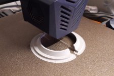
01: printing upright in two halves, flange at the bottom. I use "brim" surround for better adhesion to the printer bed. this is essential with long ports that may otherwise come loose because of the "lever" length.
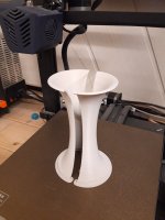
02: print complete!
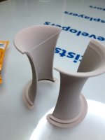
03: inaccuracies and printing layers (perpendicular to air flow) must be sanded, filled, sanded
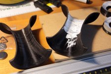
04: applying wood putty after first rough sanding of 3d prints. I use 80 grit sandpaper.
for big ports it may be possible to print one complete piece and sand, fill and smoothen the interior surface. But it's still much easier to do that with two open surfaces.
use 120 grit (and finer) sandpaper to smoothen the filled parts, once the putty is dry.
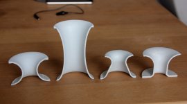
05: smoothed port halves. I like to apply a coat of grey primer to better see any remainig grates or holes.
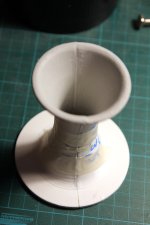
06: guing the halves. I use pva wood glue but epoxy or superglue are probably much stronger.
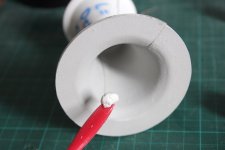
07: filling the joint gap (3d printers are not good at printing sharp edges)
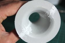
08: filled gaps
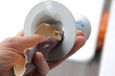
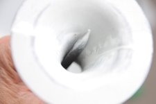
09: sanding of joint. for my very small port I use small files.
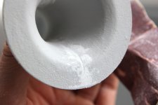
10: sanded joint
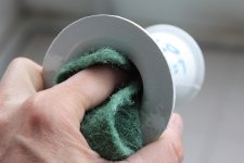
11: using 320 grit pad to further smoothen surface
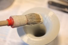
12: applying primer to fill small scratches. I use a matte primer that dries very fast and can easily be polished.

13: primed surface, some particles and brush strokes need to be smoothed out ...
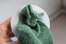
14: smoothen surface again with 320 grit pad
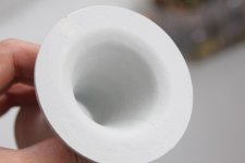
15: smooth surface of finished port (still not optically perfect, but perfectly usable in acoustic terms).
Last edited:
- Home
- Loudspeakers
- Multi-Way
- Investigating port resonance absorbers and port geometries