While my printer is doing it's thing printing the corrugator (which takes a loooong time since the gears have to be printed super slow) I thought some more on the suspension.
You are absolutely right @TNT that my designs above will have problems with linearity. Especially since the pressure from the suspension would not be uniform across the whole length of the membrane but rather just specific spots.
I got the idea of why don't I just orient the suspension like a normal speaker? Like this:
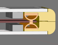
I'll probably have to print it in many smaller sections since I should probably print it standing for maximum strength like this:
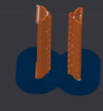
I will probably also need to add some small breathing holes in the suspension or else the air will be trapped inside and resist the compression. Also, ignore that the sliced model has bugs where it doesn't realize that the half circle should be connected to the flat edge, I can fix that later if this suspension turns out to be a better idea.
I'm also considering if I instead of having a full half cirlce like this:
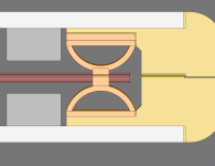
should split it into two parts like this:
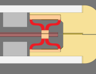
The half circle is more simple but the split would probably be more linear I think? Or maybe I am just overthinking it?
You are absolutely right @TNT that my designs above will have problems with linearity. Especially since the pressure from the suspension would not be uniform across the whole length of the membrane but rather just specific spots.
I got the idea of why don't I just orient the suspension like a normal speaker? Like this:

I'll probably have to print it in many smaller sections since I should probably print it standing for maximum strength like this:

I will probably also need to add some small breathing holes in the suspension or else the air will be trapped inside and resist the compression. Also, ignore that the sliced model has bugs where it doesn't realize that the half circle should be connected to the flat edge, I can fix that later if this suspension turns out to be a better idea.
I'm also considering if I instead of having a full half cirlce like this:

should split it into two parts like this:

The half circle is more simple but the split would probably be more linear I think? Or maybe I am just overthinking it?
Last edited:
A bagpipe orchestra / whistling contest? Calculate the Helmholtz resonance?small breathing holes in the suspension
//
Half circle is an arc which is one of the most used shapes used to carry bridges etc. - very stiff until it caves in - I think it has an initial resistance to move (like stiction) so its non-linear - your micro dynamics will be poorI'm also considering if I instead of having a full half cirlce like this:
//
If you're gonna make several tests with different suspensions, it could also be interesting to test the Occam's Razor's solution;
simple dust sealing strips like this one:

simple dust sealing strips like this one:
The first corrugator is rolling along...
No glue except I glued in the filament pins in the locking lugs so they don't fall out and get lost. The handle hadn't arrived yet when I took the pictures so I know it is missing
Also some printer problems due to printing with wet PETG filament because I didn't want to wait But it only caused cosmetic damage so didn't matter much in the end. I lost more prints due to printing way too fast. Before I've always printed functional prints with a larger nozzle where a mm here or there doesn't really matter. But now especially for the gears I have to print annoyingly slow. I'm used to print a large 20x20x20 cm part in 10 hours but just two small corrugating wheels took 16 hours
Problems to fix in next iteration:
But apart from that it works well!
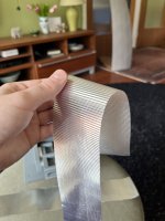
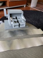
I did two initial gear sizes:
1.75 mm teeth depth + 0.667 mm ctc margin: resulted in ~ 0.64 mm peak to peak corrugations.
2.0 mm teeth depth + 0.75 ctc margin: resulted in ~ 0.74 mm peak to peak corrugations.
The corrugations are pretty shallow but with so many of them the membrane is probably stiff enough for me. So I will probably aim for ~ 0.7 - 0.8 mm corrugation peak to peak since it seems to work well.
No glue except I glued in the filament pins in the locking lugs so they don't fall out and get lost. The handle hadn't arrived yet when I took the pictures so I know it is missing
Also some printer problems due to printing with wet PETG filament because I didn't want to wait
Problems to fix in next iteration:
- The ball bearings are just slightly loose, so I need to reduce the hole size just slightly.
- The two funnel parts should be a single part instead such that I can tension the membrane flat down when rolling the corrugator to ensure it doesn't twist to either side.
- The corrugating wheels have more printer margin than they need resulting in too much spacing in between the gear rollers.
But apart from that it works well!


I did two initial gear sizes:
1.75 mm teeth depth + 0.667 mm ctc margin: resulted in ~ 0.64 mm peak to peak corrugations.
2.0 mm teeth depth + 0.75 ctc margin: resulted in ~ 0.74 mm peak to peak corrugations.
The corrugations are pretty shallow but with so many of them the membrane is probably stiff enough for me. So I will probably aim for ~ 0.7 - 0.8 mm corrugation peak to peak since it seems to work well.
Attachments
-
 IMG_0516.JPG371.5 KB · Views: 19
 -
 IMG_0515.JPG307.2 KB · Views: 14
 -
 IMG_0513.JPG349.1 KB · Views: 13
 -
 IMG_0512.JPG518.9 KB · Views: 14
 -
 IMG_0517.JPG575.5 KB · Views: 15
 -
 IMG_0518.JPG601.8 KB · Views: 12
 -
 IMG_0519.JPG557.5 KB · Views: 12
 -
 IMG_0520.JPG473 KB · Views: 14
 -
 IMG_0521.JPG455.6 KB · Views: 11
 -
 IMG_0522.JPG504 KB · Views: 10
 -
 IMG_0523.JPG499.5 KB · Views: 9
 -
 IMG_0524.JPG581.5 KB · Views: 11
 -
 IMG_0525.JPG493 KB · Views: 19
Last edited:
Ah, I forgot to mention that the test membranes I corrugated are 30 um aluminum glued on 12 um mylar.
I should probably do a test where I just have thin alu strips instead of a continous sheet since it might impact the corrugation. The easiest way to do that might be to start playing around with the plotter cutter.
And well, wet might be an exaggeration but the last time I dried the rolls was ~ 6 months ago and I haven't swapped the silica gel in the spool holder since I bought the machine. The spool holder is mostly air tight but over such a long time moisture finds its way in. Previously I've always printed when it was colder and less humid so it hasn't been a problem but now I got notifications from the humidity sensor that the filament wasn't exactly dry .
.
I should probably do a test where I just have thin alu strips instead of a continous sheet since it might impact the corrugation. The easiest way to do that might be to start playing around with the plotter cutter.
And well, wet might be an exaggeration but the last time I dried the rolls was ~ 6 months ago and I haven't swapped the silica gel in the spool holder since I bought the machine. The spool holder is mostly air tight but over such a long time moisture finds its way in. Previously I've always printed when it was colder and less humid so it hasn't been a problem but now I got notifications from the humidity sensor that the filament wasn't exactly dry
My opened rolls are on top of my printer in the filament spool holder on top of the machine. The machine is in my apartment which doesn't have an AC or a dehumidifier so currently 23 degrees C and 48 % humidity. Not crazy high like it was a few weeks ago but PETG do like things to be dry or else it gets stringy.
Most of my rolls are unopened except 1-2 rolls of grey which I keep in the spool holder + 1 roll of orange filament which has been there for years in the odd case I don't want to print in grey. I also have a heated drying box which I use before placing the filament in the spool holder.
I'm currently drying the filament that was in the spool holder now and replacing the silica gel packets and then I'll be good to go to start printing again.
Attachments
I never have problems with damp filaments as I have every filament in air tight plastic bags with a sica bag or two.
Perhaps your source of problem is the closed and heated by the printer heat dissipation filament spool holder atop of your printer.
With 30 µm aluminium, have you checked the resistance of the whole membrane?
Perhaps your source of problem is the closed and heated by the printer heat dissipation filament spool holder atop of your printer.
Yes, then the 30 µm aluminium easily "wins" over the 12 µm mylar.Ah, I forgot to mention that the test membranes I corrugated are 30 um aluminum glued on 12 um mylar.
With 30 µm aluminium, have you checked the resistance of the whole membrane?
I haven't checked the actual resistance no, but then I haven't cut a true membrane yet so that makes sense 
Based on googling I've deduced that since aluminum has 61% of the conductivity of copper. I assume that means that 30 um aluminum ~ 18 um copper. I have then used the 18 um copper thickness and plugged it into a trace resistance calculator. If that is correct then I should be able to get the end resistance close enough to my goal of 8-16 ohm given my current estimates of number of traces & trace width.
And I have a new and more simple design for the suspension. Now it looks more like a normal suspension. I'm not sure if I should just have the whole box that the membrane fits into which adds some weight or just small thin points. The latter is probably good enough to keep it aligned vertically but will the lack of left-right indexing be a problem? Or will the magnet field help align the membrane such that the traces are in between the magnets? Or I guess I could always glue the membrane to the suspension, a little glue is probably lighter than adding a lot more suspension mass.
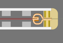
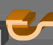
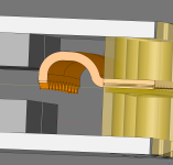
With this design the suspension the steel plates and the screws would help keep it in place so I wouldn't need to glue it to the frame which would be a huge bonus. I'd probably want to add some solid spacers in the frame to ensure it is squished the exact amount I want but that would be simple to do.
I'm still thinking if I should put connect the suspension in the middle or at the top or bottom. If I go top + bottom instead of in the middle then I could print the yellow edge frame in a single piece which adds strength and simplifies it.
Based on googling I've deduced that since aluminum has 61% of the conductivity of copper. I assume that means that 30 um aluminum ~ 18 um copper. I have then used the 18 um copper thickness and plugged it into a trace resistance calculator. If that is correct then I should be able to get the end resistance close enough to my goal of 8-16 ohm given my current estimates of number of traces & trace width.
And I have a new and more simple design for the suspension. Now it looks more like a normal suspension. I'm not sure if I should just have the whole box that the membrane fits into which adds some weight or just small thin points. The latter is probably good enough to keep it aligned vertically but will the lack of left-right indexing be a problem? Or will the magnet field help align the membrane such that the traces are in between the magnets? Or I guess I could always glue the membrane to the suspension, a little glue is probably lighter than adding a lot more suspension mass.


With this design the suspension the steel plates and the screws would help keep it in place so I wouldn't need to glue it to the frame which would be a huge bonus. I'd probably want to add some solid spacers in the frame to ensure it is squished the exact amount I want but that would be simple to do.
I'm still thinking if I should put connect the suspension in the middle or at the top or bottom. If I go top + bottom instead of in the middle then I could print the yellow edge frame in a single piece which adds strength and simplifies it.
Attachments
I think that suspension will try to make a circular motion i.e. pull the membrane apart along the short axis. Try to imagine what happens in the extreme pulling the attachment point to the max height.... eventually the point where the membrane attach will end up close the upper fastening point.
I really dint know if the xmax you plan for there is not problem... but in some sense its there...
This should in theory be better!? No inherent side ways rocking tendency...

//
I really dint know if the xmax you plan for there is not problem... but in some sense its there...
This should in theory be better!? No inherent side ways rocking tendency...
//
Good calculator, I've used this one. The result is almost the same, but you'll have to do some math with the latter.
Both methods gives 1.26 to 1.29 ohm per meter for my 3 mm wide 7 µm aluminium strips.
Four point measurements with UT611 gives 1.6 ohm though. So if you are already at the high end of 8-16 ohm theoratically, reality might be a problem.
I understand that you haven't start cutting with the Silhouette, but perhaps you can do some manual cuts?
- Home
- Loudspeakers
- Planars & Exotics
- DIY midtweeter planar, physically curved and shaded to be used in a dipole CBT

