If you are interested in switch-mode power supplies for audio amplifiers, you may want to check this link:
http://www.poweramp.ro/forum/viewtopic.php?f=14&t=2
This is an open project intended to be used for Audio Power Amplifiers, Class AB or Class D.
Full construction details for version 1 are given here:
http://www.poweramp.ro/forum/download/file.php?id=1
According to the information available, these are the mains characteristics for Version 1:
I will keep this one on my radar screen.
Regards,
http://www.poweramp.ro/forum/viewtopic.php?f=14&t=2
This is an open project intended to be used for Audio Power Amplifiers, Class AB or Class D.
Full construction details for version 1 are given here:
http://www.poweramp.ro/forum/download/file.php?id=1
According to the information available, these are the mains characteristics for Version 1:
- Output voltage of ±50V at 5A continuous (7A peak for 5 minutes or 10A peak for 1 minute).
- The maximum output power is thermally limited by the heatsink and components maximum operating temperature.
- The output ripple is about 10mV with no-load and below 200mV at 5A.
- For a step load of 1 to 5A the output voltage variation is less than 2V.
- This project does not incorporate power factor control - the current drawn from the mains will an average of 5A for 220V AC at maximum output power and 10A for 110V.
- The average efficiency is 87% and the efficiency at maximum output power is 90.7%
I will keep this one on my radar screen.
Regards,
argh!
It's a dangerous site!!!
An externally hosted image should be here but it was not working when we last tested it.
It's a dangerous site!!!
argh!
It's a dangerous site!!!
I do not get this message and besides having a Barracuda system we have a very strict policy in our office - our IT guys are really paranoid about dangerous sites.
I have no clue why you got such a message...
argh!
It's a dangerous site!!!
that's because somebody who likes me too much wanted to "help" me in the development of this project. i already traced the attackers, report them and i will fix the problem.
untill then, access just the following link: http://www.poweramp.ro/forum/viewforum.php?f=14
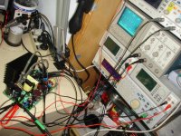
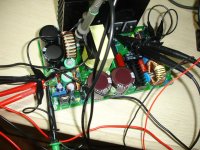
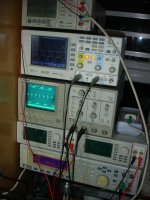
some test results. photos can speak for themself. on top of the instuments stack, is the Power Analyzer. this measure the input current, voltage, power factor and power. next, the upper scope, the digital one monitor the output vawe, directly on the transformer pins. the lower one, has one channel DC coupled on the bridge, probes set to x10 and scope at 5V/div, 5uS and another channel AC coupled, probes x10, 5V/div, 5us and is connected to vbus. what can see there is the AC ripple. the two multimeters from below the analog scope measures the output voltages, one for positive, one for negative. at the bottom, with the audio analyzer i measure the output voltage ripple at 3, 5 and 6A. the probe is x10, so multiply with 10.
on the other side lays the DC electronic load. because is rated at just 300W, i connected in series 2 power resistors to limit the maximum power, otherwise i cannot load the smps with more than 300W. the current reading is accurate, but the voltage reading should be added to the voltage drop on the resistors, wich is proportional with the current. anyway for accurate voltage reading, i use those 2 lab. multimeters below the scope.
i can attach just few photos, for more details, please follow the link http://www.poweramp.ro/forum/viewtopic.php?f=14&t=2&p=11#p11
Attachments
Last edited:
Hello CNX
I am interested in getting the kit you are offering and get my soldering iron going.
I see on the website that it is possible to order the ready-made SMPS with the optional E55 transformer.
Is this option applicable for the KIT version? Please advise.
Thanks!
i'm opened for any combination. please contact me and we disscuse about.
the output voltage depends on the transformer turns ratio, output inductor value, capacitor voltage and control loop setting. so, is possible to get any output voltage from let's say +-30 to +-80V by changing this components or without chaning can get +-50V in the range of +-20%.
more infos, and test photos here: http://www.poweramp.ro/forum/viewtopic.php?f=14&t=2
access this link directely, since the main page will throw you to some fake site, thanks to the concurent team which spend time trying virus attacks on my site instead of developing their product.
more infos, and test photos here: http://www.poweramp.ro/forum/viewtopic.php?f=14&t=2
access this link directely, since the main page will throw you to some fake site, thanks to the concurent team which spend time trying virus attacks on my site instead of developing their product.
it is possible to provide other voltages than +-50V, if the difference is biger than +-20% than i have to use transformer wounded for that specific voltage. when you order, please mention what voltage you need, so i can use the proper transformer for the board, or just contact me on pm for more details.
all the outputs, are regulated, including the aux. voltage output.
all the outputs, are regulated, including the aux. voltage output.
- Status
- This old topic is closed. If you want to reopen this topic, contact a moderator using the "Report Post" button.
- Home
- Vendor's Bazaar
- Open project: ±50v smps for audio amplifiers