insulation is not ok. You need to use sil pad or kapton + TO-220 bush to isolate mounting screw + the heatsink from the metal tab of MUR860. otherwise its a hazard if heatsink touches any metal part or flesh
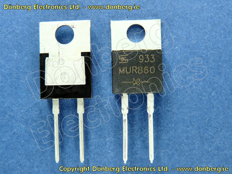
MUR860 is 8A diode so its ok, insulation is ok.
On both diodes cathode is right pin, so i guess its ok to use them instead.
 .. ..
.. .. i mean insulation is not problem
 Here is an option with SK104/ SK129 heatsinks that are very good and come with pin that can be soldered to PCB. Heat sink is grounded.
SK 104 38,1 STIS, Extruded heatsinks for PCB mounting, Heatsinks f.cool, Fischer Elektronik
SK 129 ... STC<br />SK 129 ... STIC<br />SK 129 ... STCB, Extruded heatsinks for PCB mounting, Heatsinks f.cool, Fischer Elektronik
SK 104 38,1 STIS, Extruded heatsinks for PCB mounting, Heatsinks f.cool, Fischer Elektronik
SK 129 ... STC<br />SK 129 ... STIC<br />SK 129 ... STCB, Extruded heatsinks for PCB mounting, Heatsinks f.cool, Fischer Elektronik
Attachments
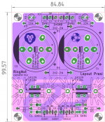
Prasi, that new PCB layout looks nice! Bigger heatsinks would allow the use of Super High Vfwd diodes that were so fashionable and trendy in the 1990s. Big current and high Vfwd means big power dissipation in the diodes, which means you want big heatsinks.
Paranoid builders might want to install a thin rectangular sheet of insulation (e.g. mylar) between the heatsinks and the top of the PCB. Just in case the soldermask rubs away over time. If a short does occur, the well grounded heatsink gives a very low impedance current path, which hopefully causes the fuse(s) to blow very quickly.
Paranoid builders might want to install a thin rectangular sheet of insulation (e.g. mylar) between the heatsinks and the top of the PCB. Just in case the soldermask rubs away over time. If a short does occur, the well grounded heatsink gives a very low impedance current path, which hopefully causes the fuse(s) to blow very quickly.
Hi Mark, this is all good stuff. I'm going to try building the Ring Not power supply.
I have a couple of questions. I'm not sure how to go about changing the configuration
to use the AnTek AN-0212-25VA 12V Transformer. I want to use it to for the Marsh
Headphone Amp. Which should get me about +/- 14-15VDC at the output to drive
the amp boards.
I'll have to run around and find where or how you optimized it for your AN-2222
transformers.
As you are the designer of this how would it compare to something like using
these eval boards: http://www.ti.com/lit/ug/slvu741a/slvu741a.pdf
I have your:
doc rev A01
pcb rev A01
If I can then design these PCB and have them made for the project for me,
then for my little girls head phone amp also. I should have leftovers for
other people too.
I assume the layout would be the same and only some of the values would
change. If you don't mind helping out a bit I would offer these at modest
price to other DIYAudio folks. After expenses I would ask enough for a
cup of Starbucks Coffee for each of us.
At least that jolt of caffeine would enable another day of alert analysis.
Cheers,
I recommend you start a brand new thread with a catchy title like "Help with power supply for little girls head phone amp" and tap into the collective wisdom of all 200K+ diyAudio members.
I'm a big believer in the collective wisdom, and I'm not a big believer in private lessons.
Concerning RingNot PCB, the actual topic of the thread you're reading now, there are a few reasons why I recommend ONLY the Antek AN-2222 or its electrostatic shielded brother the AS-2222, with the RingNot PCB:
To use RingNot with a new, different transformer, your circuit designer will need to optimize the anti-oscillation snubber component values for that new transformer.
_
I'm a big believer in the collective wisdom, and I'm not a big believer in private lessons.
Concerning RingNot PCB, the actual topic of the thread you're reading now, there are a few reasons why I recommend ONLY the Antek AN-2222 or its electrostatic shielded brother the AS-2222, with the RingNot PCB:
1. It has the right output voltage and the right VA rating, for a two channel power amp using LM3886's ("chip amps")
2. It's the exact transformer I used during design and testing of RingNot
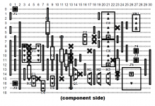
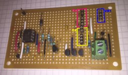
3. The anti-oscillation snubber component values (C1, R2, C2) shown on the RingNot schematic, are tuned & optimized for the AN-2222. They were physically installed and measured and tweaked, in-circuit with an AN-2222, using a DIY "Cheapomodo" test jig. Mine is shown in the attachments below; many dozens of other diyAudio members have built their own Cheapomodo, on PCBs, pluggy-innie solderless breadboards, perfboard scraps, etc.
2. It's the exact transformer I used during design and testing of RingNot
3. The anti-oscillation snubber component values (C1, R2, C2) shown on the RingNot schematic, are tuned & optimized for the AN-2222. They were physically installed and measured and tweaked, in-circuit with an AN-2222, using a DIY "Cheapomodo" test jig. Mine is shown in the attachments below; many dozens of other diyAudio members have built their own Cheapomodo, on PCBs, pluggy-innie solderless breadboards, perfboard scraps, etc.
To use RingNot with a new, different transformer, your circuit designer will need to optimize the anti-oscillation snubber component values for that new transformer.
_
Attachments
- Status
- This old topic is closed. If you want to reopen this topic, contact a moderator using the "Report Post" button.
- Home
- Vendor's Bazaar
- RingNot: power supply for chip amps. Bare PCBs and/or assembled+tested units