Hi Guys,
As a general update, all the boards are up and running, and in spite of the fact that I didn't think there was much room for improvement with The Wire series, the new PSU has really brought overall performance up to whole new level.
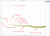
The TPS7A3301 regs aren't just a little better than the old LM3XX series regs, they are roughly an order of magnitude better. The FFT of the PSU output is better looking than the output of most actual headphone amplifiers, which is really cool")
This improvement trickles through to the performance of the SE-SE and BAL-BAL amplifiers by way of lower noise, better crosstalk, and improved startup and shutdown characteristics.
The supply improvements on the LPUHP have also been very beneficial from a noise standpoint, but even more from a startup and shutdown behavior perspective. The original LPUHP had a bit of a transient at startup and shutdown, which has been completely eliminated with the new regulator setup. The symmetrical positive and negative regulators have exactly the same startup and shutdown times, which is the reason for the improvement.
I've got tonnes of info to post, so this will take a few posts to get through. I'll break down the pictures and results by board, starting with the PSU.
Once all the boards and test results are posted here, I will be sending out payment requests to everyone on the main list. Expect to start seeing them this evening!
Cheers,
Owen
As a general update, all the boards are up and running, and in spite of the fact that I didn't think there was much room for improvement with The Wire series, the new PSU has really brought overall performance up to whole new level.
The TPS7A3301 regs aren't just a little better than the old LM3XX series regs, they are roughly an order of magnitude better. The FFT of the PSU output is better looking than the output of most actual headphone amplifiers, which is really cool
This improvement trickles through to the performance of the SE-SE and BAL-BAL amplifiers by way of lower noise, better crosstalk, and improved startup and shutdown characteristics.
The supply improvements on the LPUHP have also been very beneficial from a noise standpoint, but even more from a startup and shutdown behavior perspective. The original LPUHP had a bit of a transient at startup and shutdown, which has been completely eliminated with the new regulator setup. The symmetrical positive and negative regulators have exactly the same startup and shutdown times, which is the reason for the improvement.
I've got tonnes of info to post, so this will take a few posts to get through. I'll break down the pictures and results by board, starting with the PSU.
Once all the boards and test results are posted here, I will be sending out payment requests to everyone on the main list. Expect to start seeing them this evening!
Cheers,
Owen
PSU
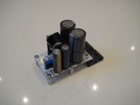
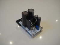
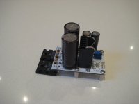
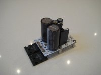
PSU Results:
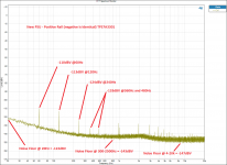
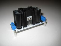
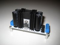
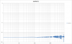
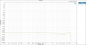
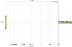
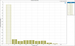
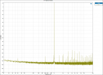
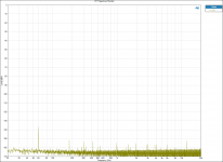
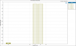
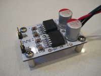
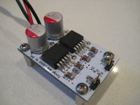
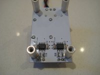
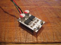
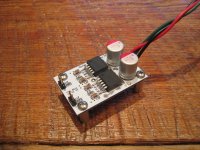
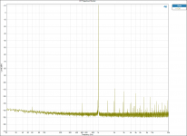
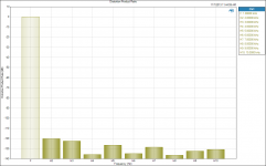
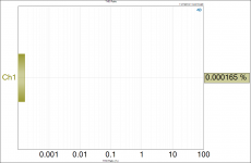
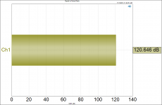
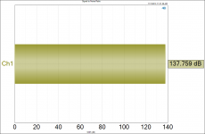
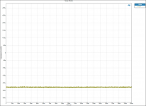
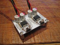
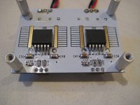
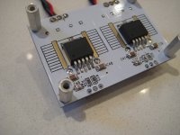
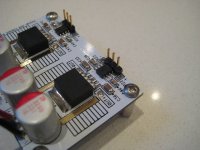
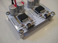
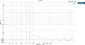
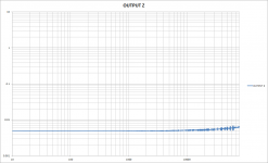
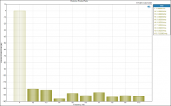
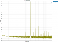
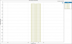
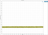
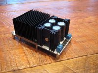
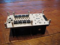
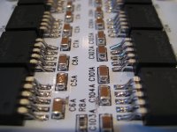
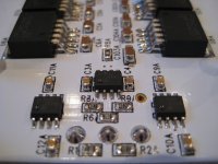
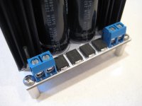
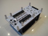
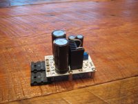
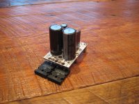
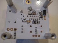
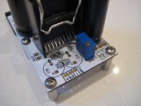
Below are a few pictures of the fully built PSU and an FFT of the output of the positive rail (both rails are identical).
The overall noise floor is roughly 10-12dB lower than the LM3XX regulators, and the rectification fundamental and harmonics are as much as 30dB lower!
Although it's not shown the output impedance is also quite a bit lower, giving improved load regulation.
Also attached below is the complete BOM for building the PSU. The BOM is very comprehensive, so it's worth reading it over to make sure you actually need everything on the list.
It's also worth noting that if you guys arrange a group buy for these parts, the total cost could be reduced by about half.
More to come!
PSU Results:
Below are a few pictures of the fully built PSU and an FFT of the output of the positive rail (both rails are identical).
The overall noise floor is roughly 10-12dB lower than the LM3XX regulators, and the rectification fundamental and harmonics are as much as 30dB lower!
Although it's not shown the output impedance is also quite a bit lower, giving improved load regulation.
Also attached below is the complete BOM for building the PSU. The BOM is very comprehensive, so it's worth reading it over to make sure you actually need everything on the list.
It's also worth noting that if you guys arrange a group buy for these parts, the total cost could be reduced by about half.
More to come!
Attachments
SE-SE
On to the SE-SE
There is minimal overall change on this board, meaning the old BOM and build thread is still applicable:
"The Wire" Headphone Amp Build Wiki - diyAudio
I haven't measured the old and new board with the new PSU, but I don't expect any meaningful differences between them. The only change is the addition of another full layer ground plane, which may help to slightly improve crosstalk and slightly reduce noise, but I haven't directly compared the two.
All the improvements shown in the measurements below are a result of the better PSU.
Also note that all THD measurements are limited by the AP output generators, and not by the headphone amp itself.
Pictures to follow.
Attachments
-
 SE-SE OUTPUT IMPEDANCE.png59.6 KB · Views: 280
 -
 THD Ratio v freq 4vrms.png61.5 KB · Views: 274
 -
 DC OUTPUT - AP input.png80.9 KB · Views: 256
 -
 Signal to Noise Ratio 7.2VRMS.png46.2 KB · Views: 250
 -
 Signal to Noise Ratio 2VRMS.png46.8 KB · Views: 274
 -
 THD Ratio 4VRMS.png73.7 KB · Views: 302
 -
 Distortion Product Ratio 4VRMS.png50.1 KB · Views: 362
 -
 FFT Spectrum Monitor 4vrms 50R.png107.9 KB · Views: 356
 -
 FR 2VRMS.png66.2 KB · Views: 338
 -
 FFT Spectrum Monitor - OUTPUT AP INPUT.png105.4 KB · Views: 748
SE-SE Pictures
See attached for pictures and more measurements of the complete SE-SE
See attached for pictures and more measurements of the complete SE-SE
Attachments
-
 MOD Distortion Product Ratio 4VRMS IMD 60-7k 4 to 1.png49.1 KB · Views: 227
 -
 DFD Distortion Product Ratio 4VRMS IMD 80-12.5k.png43.5 KB · Views: 296
 -
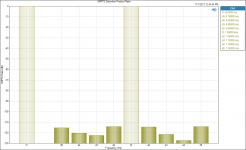
 SMPTE Distortion Product Ratio 4VRMS IMD 60-7k 4 to 1.png54.9 KB · Views: 217
 -
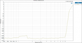
 THD Ratio v level.png74.2 KB · Views: 265
 -
 IMG_9199.JPG236.9 KB · Views: 500
 -
 IMG_9200.JPG242.4 KB · Views: 571
 -
 IMG_9201.JPG207.7 KB · Views: 516
 -
 IMG_9229.JPG380.9 KB · Views: 476
 -
 IMG_9230.JPG373 KB · Views: 422
Last edited:
BAL-BAL
All the same comments made above for the SE-SE apply to the BAL-BAL variant as well. The BOM is the same and the Wiki link above is also the same.
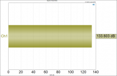
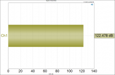
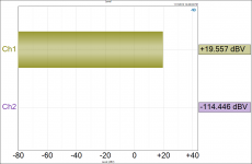
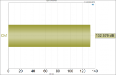
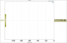
There is a newer measurement for the BAL-BAL which is labelled as "crosstalk". The actual crosstalk should be the driven channel level minus the undriven channel level, which is roughly 134dB of channel separation.
This was measured driving a 50 ohm load with both channels sharing a single PSU. I don't think there's much point in running the BAL-BAL with a dual PSU, unless you just like the idea of it
Pictures to follow...
All the same comments made above for the SE-SE apply to the BAL-BAL variant as well. The BOM is the same and the Wiki link above is also the same.
There is a newer measurement for the BAL-BAL which is labelled as "crosstalk". The actual crosstalk should be the driven channel level minus the undriven channel level, which is roughly 134dB of channel separation.
This was measured driving a 50 ohm load with both channels sharing a single PSU. I don't think there's much point in running the BAL-BAL with a dual PSU, unless you just like the idea of it
Pictures to follow...
Attachments
-
 FFT 4VRMS.png106.2 KB · Views: 263
 -
 Distortion Product Ratio 4VRMS.png50.7 KB · Views: 255
 -
 THD Ratio 5VRMS.png73.3 KB · Views: 198
 -
 Signal to Noise Ratio 2VRMS.png46.8 KB · Views: 185
 -
 Signal to Noise Ratio - 14.4VRMS.png46.5 KB · Views: 172
 -
 THD Ratio v Freq.png62.7 KB · Views: 206
 -
 BAL-BAL OUTPUT IMPEDANCE.png57.8 KB · Views: 202
 -
 Crosstalk.png46.4 KB · Views: 192
 -
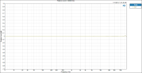 FR - 2VRMS.png66.2 KB · Views: 202
 -
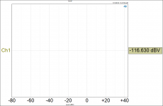 Output Level - No Input dBV.png41.2 KB · Views: 400
BAL-BAL
And a few more...
And a few more...
Attachments
-
 MOD Distortion Product Ratio 4VRMS IMD 60-7k 4 to 1.png49.1 KB · Views: 167
 -
 DFD Distortion Product Ratio 4VRMS IMD 80-12.5k.png43.5 KB · Views: 167
 -
 DC OFFSET - No Input.png72.5 KB · Views: 209
 -
 SMPTE Distortion Product Ratio 4VRMS IMD 60-7k 4 to 1.png54.9 KB · Views: 163
 -
 IMG_9228.JPG371 KB · Views: 419
 -
 IMG_9198.JPG263.1 KB · Views: 399
 -
 IMG_9197.JPG257.1 KB · Views: 386
 -
 IMG_9196.JPG249.9 KB · Views: 454
 -
 IMG_9195.JPG268.6 KB · Views: 482
 -
 THD Ratio v level.png74.2 KB · Views: 215
Last edited:
LPUHP V2
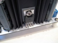
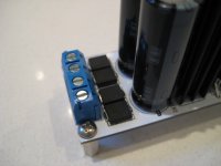
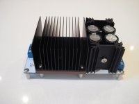
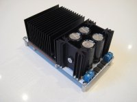
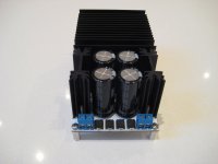
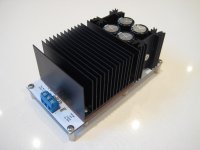
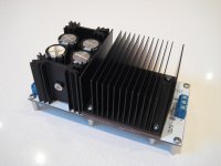
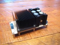
Next up is the LPUHP V2 which underwent a bit of a redesign for the power supply and regulators, and has an improved heatsinking arrangement for the output stage.
I have attached all the usual measurements, as well as a new BOM to cover all the changes from V1.
The noise floor is significantly lower compared to V1, and with a larger transformer (50VA to 100VA) you will get a little more output power before clipping. These measurements can be compared to the original ones in the first LPUHP thread.
There are some notes in the BOM worth reading. If you want to build the SE input variant, you need to omit the first two op-amps and their associated parts, and re-select the resistors to get the gain you want for the remaining stage. I'll elaborate on this later in a proper Wiki.
The heatsink for the output stage is not absolutely needed. If you lift the BW pin on the output buffers and don't run a high duty cycle, then you probably won't need a heatsink.
The heatsink in the BOM does not look like the one in the pictures. Neither DK nor Mouser carry that particular heatsink, but you can get one from Newark if you like the way it looks
241214B91200G - AAVID THERMALLOY - HEAT SINK | Newark
There are also much cooler looking ones if you want to add some "bling":
Online Catalog - DCC - DCC60S
Heat Sinks for Surface Mount Devices ? Overview - Cool Innovations
The design is intended for a "half brick" size heatsink so anything compatible with that should work as long as you get the orientation right!
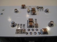
Finally, there is a little bit of bad news. There was a copper to copper short on the bottom of these boards that didn't get caught in DRC for some reason, so I will need to make two small cuts on each board to fix the short. I will perform this small fix on each board, and test each one to ensure it's good to go. There will, however, be two small nicks in the bottom of each board so if you're fussy about looks and want to cancel your order, then please adjust accordingly. You can see the cuts in the pictured provided if you look closely by the first pair of output stage bypass caps.
Last up is the high power lateral FET amp!
Next up is the LPUHP V2 which underwent a bit of a redesign for the power supply and regulators, and has an improved heatsinking arrangement for the output stage.
I have attached all the usual measurements, as well as a new BOM to cover all the changes from V1.
The noise floor is significantly lower compared to V1, and with a larger transformer (50VA to 100VA) you will get a little more output power before clipping. These measurements can be compared to the original ones in the first LPUHP thread.
There are some notes in the BOM worth reading. If you want to build the SE input variant, you need to omit the first two op-amps and their associated parts, and re-select the resistors to get the gain you want for the remaining stage. I'll elaborate on this later in a proper Wiki.
The heatsink for the output stage is not absolutely needed. If you lift the BW pin on the output buffers and don't run a high duty cycle, then you probably won't need a heatsink.
The heatsink in the BOM does not look like the one in the pictures. Neither DK nor Mouser carry that particular heatsink, but you can get one from Newark if you like the way it looks
241214B91200G - AAVID THERMALLOY - HEAT SINK | Newark
There are also much cooler looking ones if you want to add some "bling":
Online Catalog - DCC - DCC60S
Heat Sinks for Surface Mount Devices ? Overview - Cool Innovations
The design is intended for a "half brick" size heatsink so anything compatible with that should work as long as you get the orientation right!
Finally, there is a little bit of bad news. There was a copper to copper short on the bottom of these boards that didn't get caught in DRC for some reason, so I will need to make two small cuts on each board to fix the short. I will perform this small fix on each board, and test each one to ensure it's good to go. There will, however, be two small nicks in the bottom of each board so if you're fussy about looks and want to cancel your order, then please adjust accordingly. You can see the cuts in the pictured provided if you look closely by the first pair of output stage bypass caps.
Last up is the high power lateral FET amp!
Attachments
-
 LPUHP OUTPUT IMPEDANCE.png55.4 KB · Views: 300
 -
 THD Ratio vs output power 8R zoom.png51.1 KB · Views: 286
 -
 THD Ratio v freq.png61.7 KB · Views: 488
 -
 Signal to Noise Ratio 15W.png46.5 KB · Views: 200
 -
 Signal to Noise Ratio 1W.png47 KB · Views: 218
 -
 THD Ratio 5VRMS OUT.png40.8 KB · Views: 247
 -
 Distortion Product Ratio 4VRMS out.png50.6 KB · Views: 323
 -
 FFT Spectrum Monitor 1W.png112.1 KB · Views: 552
 -
 FR - 1W.png66.1 KB · Views: 262
 -
 FFT Spectrum Monitor - 50R input.png102.4 KB · Views: 472
LPUHP V2
More LPUHP images and measurements
More LPUHP images and measurements
Attachments
-
 IMG_9167.JPG188.9 KB · Views: 347
 -
 IMG_9168.JPG220.2 KB · Views: 357
 -
 IMG_9169.JPG201.6 KB · Views: 356
 -
 IMG_9170.JPG217.8 KB · Views: 838
 -
 IMG_9166.JPG200.5 KB · Views: 425
 -
 IMG_9165.JPG217.9 KB · Views: 426
 -
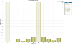 SMPTE Distortion Product Ratio.png54.2 KB · Views: 211
 -
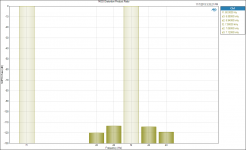 MOD Distortion Product Ratio.png49.3 KB · Views: 205
 -
 DFD Distortion Product Ratio.png43 KB · Views: 243
 -
 DC offset 8R AP input.png91.5 KB · Views: 313
LPUHP V2
And a few more...
And a few more...
Attachments
-
 IMG_9212.JPG209.1 KB · Views: 250
 -
 IMG_9213.JPG383.8 KB · Views: 257
 -
 IMG_9214.JPG371.1 KB · Views: 239
 -
 IMG_9215.JPG299.6 KB · Views: 244
 -
 IMG_9211.JPG231.9 KB · Views: 243
 -
 IMG_9210.JPG279 KB · Views: 1,079
 -
 IMG_9209.JPG274.1 KB · Views: 1,019
 -
 IMG_9208.JPG252 KB · Views: 1,032
 -
 IMG_9207.JPG197 KB · Views: 1,039
 -
 IMG_9171.JPG232.2 KB · Views: 1,073
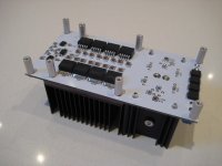
Lateral FET Amp
I'm not quite done with the measurements for the high power amp just yet, but here are some pictures, and the build guide attached for those who didn't know about it.
The BOM and the boards are identical to the original version, with the addition of an internal ground plane
Payment requests will be going out throughout the day tomorrow!
Cheers,
Owen
Attachments
-
 IMG_9216.JPG313.1 KB · Views: 239
 -
 IMG_9217.JPG375.4 KB · Views: 229
 -
LME Amp Assembly Instructions.pdf163.3 KB · Views: 139
-
LME AMP SCHEMATIC.pdf32.7 KB · Views: 143
-
 IMG_9206.JPG224 KB · Views: 255
 -
 IMG_9205.JPG223.2 KB · Views: 232
 -
 IMG_9175.JPG194.8 KB · Views: 180
 -
 IMG_9174.JPG207 KB · Views: 196
 -
 IMG_9173.JPG211.6 KB · Views: 245
 -
 IMG_9172.JPG213.5 KB · Views: 301
Right you are!
here it is
As a side note, the BOM doesn't have any "price optimization" done at all. Most of the active components (and some of the passives) are a bit cheaper from Mouser, and everything on the list purchased in larger quantities would really get the price down.
If you went in for 100 kits, you could easily get the price down to less than $75 total per channel.
Cheers,
Owen
Attachments
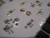
Wow! Impressive stuff and your SMD soldering is looking top-notch as usual
I was wondering if Owen has got an oven that he's using for some of it now ... Just there is a bit of excess solder that a perfectionist like Owen probably wouldn't leave if he did it all by hand. But he did mention that he'd done some by hand so maybe he was just in a hurry when building these (and by the sound of it that's probably the case). Judging on previous photos I've seen of his work this is a different solder to what he has used in the past too perhaps ... it's so shiny!
Cheers,
Chris
Last edited:
Thanks for all encouragement guys! It has been a very long road to here, but it looks like the end is in sight.
I'm all set to start packing and shipping the boards, so I will be sending out payment requests and posting detailed instructions here throughout the day today.
Q&A:
Thanks sek!
It's not my best work, as I was in a bit of a rush to get all five boards built and tested, but I'll take it
Hi Nikitas,
I am indeed using the TPS7A3301 for both the positive and negative rails. If you use a dual secondary transformer, then you basically float both regulators all the way to the outputs, and then just treat them like two floating voltage sources that you can connect any way you want. In this case, for the positive rail, the negative output becomes GND, and what used to be GND becomes the positive output. There are some great advantages to this, as both regulators now have the exact same noise, output impedance, startup and shutdown time, and are generally more symmetrical than two complimentary regulators are.
I also use the same trick on the new LPUHP with a pair of LT1185 regulators which are also both negative regs.
Impressive observational skills Chris!
No oven yet... but some of the stuff I've been working on makes me wish I had one!
As for the bulbous solder joints, I blame my rushing, and the fact that I ran out of my favorite Cardas solder and am stuck using this odd radio shack stuff which isn't the best.
I had the solder wick out and started to clean up some of the joints, but then decided I'd have plenty of time to do that after I shipped out everyone's goodies
Thanks again to everyone here for all the support and positive comments, and I'm looking forward to shipping these out and having people build them all up!
Cheers,
Owen
I'm all set to start packing and shipping the boards, so I will be sending out payment requests and posting detailed instructions here throughout the day today.
Q&A:
Impressive work Owen, thank you.
Keep it up.
Thanks sek!
Wow! Impressive stuff and your SMD soldering is looking top-notch as usual
It's not my best work, as I was in a bit of a rush to get all five boards built and tested, but I'll take it
Hi Owen, which positive reg did you use in your psu? As far as I know, ti doesn't produce a positive equivalent to Tps47a3301 reg in to-220 package.
Hi Nikitas,
I am indeed using the TPS7A3301 for both the positive and negative rails. If you use a dual secondary transformer, then you basically float both regulators all the way to the outputs, and then just treat them like two floating voltage sources that you can connect any way you want. In this case, for the positive rail, the negative output becomes GND, and what used to be GND becomes the positive output. There are some great advantages to this, as both regulators now have the exact same noise, output impedance, startup and shutdown time, and are generally more symmetrical than two complimentary regulators are.
I also use the same trick on the new LPUHP with a pair of LT1185 regulators which are also both negative regs.
I was wondering if Owen has got an oven that he's using for some of it now ... Just there is a bit of excess solder that a perfectionist like Owen probably wouldn't leave if he did it all by hand. But he did mention that he'd done some by hand so maybe he was just in a hurry when building these (and by the sound of it that's probably the case). Judging on previous photos I've seen of his work this is a different solder to what he has used in the past too perhaps ... it's so shiny!
Cheers,
Chris
Impressive observational skills Chris!
No oven yet... but some of the stuff I've been working on makes me wish I had one!
As for the bulbous solder joints, I blame my rushing, and the fact that I ran out of my favorite Cardas solder and am stuck using this odd radio shack stuff which isn't the best.
I had the solder wick out and started to clean up some of the joints, but then decided I'd have plenty of time to do that after I shipped out everyone's goodies
Thanks again to everyone here for all the support and positive comments, and I'm looking forward to shipping these out and having people build them all up!
Cheers,
Owen
- Home
- Vendor's Bazaar
- "The Wire" Official Boards for All Projects Available Here! BAL-BAL, SE-SE, LPUHP