......new PCB rev2.0 , I can't stay to do nothing
Happy New Year !
Alex.
Thanks Alex, you're true DIY

Happy New Year and many successful project for you too.

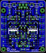
P.S. ALF08N16(20)V & ALF08P16(20)V perfectly fits to this PCB too.
")

i don't like fuses after capacitors.
There are more capacitors after fuses.
Besides these are Time Lag fuses with better conductive characteristics than Fast ones.

Alex.. nice.. but how to trim offset..??
Trimmers first, than measure, resistors in final.
Today I did listen to VSSA one channel and I have to say it has a potential.
Because I have installed VAS transistors on the main heatsink I had to use ref zener as bias spreader and it works, 100 mA bias for the outputs is completely stable. VAS bias goes from 10 mA (cold start) to 15 mA working conditions and stayed stable also on small heatsink as it is.
Measured output impedance and it is negative: at 4 Vrms unloaded I got 4,05 Vrms loaded with 4 ohm resistor.
Tomorrow I'll do it again, probably the positive probe was too close to sources pin of the output mosfets and I measured also voltage drop on that lead.
Otherwise it worked fluently.
i was referring at Alex's pcb, where the output mosfets are connected directly with the fuses
It has Vrail --> caps --> fuse --> mosfet
Typical super-SQ-guru (
Vrail --> fuse --> caps --> mosfet
There are 1 uF capacitors after fuses on Alex's PCB 2.0
with a little mod you can easy have 1101uF
Only a picky advice
You mean like in schs from my signature's links?
But I didn't want to put more than 1 uF after fuses here in VSSA, made on purpose this way. You don't know why?

.....Thanks L.C , another PCB , attached
Happy New Year to all diy members ! Alex.
Hi Alex,
I love this last one. Could you just include solder pad for trimmer located on 15K resistors. One fine tuned done resistor equivalent value take place on 15k location.
Marc
.....Thanks L.C , another PCB , attached
Happy New Year to all diy members ! Alex.
Alex by using 1uf with 7.5mm pin spacing tou could improve output layout and feedback return.
Marc
LC, according to nice Alex mm work, do you think VAS tansistors heatsink are sufficient? They mesure 15x10mm surface. On ebay wa can find those unit that are 20mm long.
Marc
Hi Marc
VAS BJTs have 0.6 W dissipation, at 45°C final temperature, we need heatsink with 30 K/W temp koeficient, so check the specifications.
If VAS BJTs are on the top of PCB, 120 ohm bias spreader is OK, if they're on the main heatsink, ref zener (shunt regulator) is a must. I measured Vgg=1,5165 V at 100 mA output bias.
Measurements from today gives similar results like yesterday. 100 kHz 16 Vrms on 8 ohm (2 Arms) gives +5 mV when loaded, so VSSA has negative output impedance.
At 1 MHz 16 Vrms on 8 ohm I measured 100 mV voltage drop on output impedance, that gives us 50 mohm output impedance or damping factor 160.
-3dB lower roll-off is at 6 Hz so maybe I'll higher feedback impedance to 2,2k/100 ohm to go down to 3 Hz.
I'll assemble cmos square wave generator to test 10 kHz to 1 MHz squares response.
Regards L.C.

can you test also 100Hz and 1kHz damping factor?
From 20 Hz to 10 kHz VSSA gives +3 mV when loaded, so stil negative output impedance.
- Home
- Vendor's Bazaar
- VSSA Lateral MosFet Amplifier