Hi Russ, I plan to build Buffalo III DAC for my hifi system. I use 02 channel and coaxial input only. Could you recommend which kit and accessory I need to order? Kit is completed one (I just have to do wiring) or there are some parts I need to solder in?
Can you ship directly to Vietnam?
Thank you.
Can you ship directly to Vietnam?
Thank you.
Thank you LeonvB, could you please advise if below order is fit my need (02 channel, 01 single Coaxial input):
1. IVY-III Kit + One Placid HD BP Kit Combo
2. Single S/PDIF Level Converter Kit
3 Buffalo-III DAC Module (Assembled and Tested) + Trident Regulator Set (Assembled and Tested)
1. IVY-III Kit + One Placid HD BP Kit Combo
2. Single S/PDIF Level Converter Kit
3 Buffalo-III DAC Module (Assembled and Tested) + Trident Regulator Set (Assembled and Tested)
Thank you Leon, Thank you Ed.
Finaly, I decided to purchase
1. IVY-III Kit + One Placid HD BP Kit Combo
2. 4 input S/PDIF Level Converter Kit -> For future use
3 Buffalo-III DAC Module (Assembled and Tested) + Trident Regulator Set (Assembled and Tested)
4. TOSKLINK module
5. Placid HD BP Kit for B3 because Placid HD is out of stock.
Now discussing on purchasing matter, can not wait to have it in hand")
Finaly, I decided to purchase
1. IVY-III Kit + One Placid HD BP Kit Combo
2. 4 input S/PDIF Level Converter Kit -> For future use
3 Buffalo-III DAC Module (Assembled and Tested) + Trident Regulator Set (Assembled and Tested)
4. TOSKLINK module
5. Placid HD BP Kit for B3 because Placid HD is out of stock.
Now discussing on purchasing matter, can not wait to have it in hand
I thought Placid HD BP was build with 2 Placids HD, only the negative side have diferent transistors and regulators. In that case its possible to change the negative side to make it a positive dual power supply with a 15 VAC 9V secundaries transformer to deliver 2 x 5.25V. My guess
Regards
Regards
I thought Placid HD BP was build with 2 Placids HD, only the negative side have diferent transistors and regulators. In that case its possible to change the negative side to make it a positive dual power supply with a 15 VAC 9V secundaries transformer to deliver 2 x 5.25V. My guess
Regards
I ordered it with same thinking. I plan to use half of it (positive side) to feed B3.
Am I wrong? Please advise.
SPDIF in
Hi,
My buffalo III DAC has been working well with the single SPDIF converter input and my M-Audio FW410 SPDIF out. I recently purchased a M-Audio Delta 1010 and hooked up the SPDIF out from that. Both lock and mute LEDs stay on and no sound comes out. The Delta 1010 SPDIF out works fine when run to my Wadia 860 so that seems to be OK. Any ideas what is going on here? The Buffalo is set up in stereo mode with one SPDIF input.
Thanks, Mike
Comparison to Musical Fidelity
Hi
I would like to build a BIII with a Ligato but I'll have to get rid of my existing dac Musical fidelity KW DM25 due to domestic rules. Could some one with experience elaborate on how these two would compare before I commit? I use a AVC for a pre and a aleph J.
Thanks
Hi
I would like to build a BIII with a Ligato but I'll have to get rid of my existing dac Musical fidelity KW DM25 due to domestic rules. Could some one with experience elaborate on how these two would compare before I commit? I use a AVC for a pre and a aleph J.
Thanks
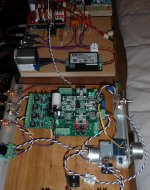
At the moment I use the 4 way Switch module to select between sources as per the photo.
I want to use my Arduino to switch sources using the same inputs that the Switch Module uses being (pins B0=6 & B1=8) I have tried what I thought would work but it clearly didn't so I expect my understanding of how the switch Module works is defective
Can anyone advise me how I might do the switching with the Arduino via the Switch module input.
Attachments
At the moment I use the 4 way Switch module to select between sources as per the photo.
I want to use my Arduino to switch sources using the same inputs that the Switch Module uses being (pins B0=6 & B1=8) I have tried what I thought would work but it clearly didn't so I expect my understanding of how the switch Module works is defective
Can anyone advise me how I might do the switching with the Arduino via the Switch module input.
I think that is just a 4-way spdif to ttl level converter. It is not a switch module. In Arduino you will need to program register 18 to select the corresponding spdif input pin
I think that is just a 4-way spdif to ttl level converter. It is not a switch module. In Arduino you will need to program register 18 to select the corresponding spdif input pin
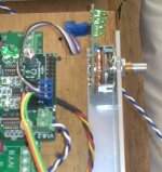
This is the input selector I'm referring to, I was hoping to finish climbing my low tech mountain before climbing your high tech mountain
DimDim
I started this journey before I found out about HiFiduino & I would like to finish it, if nothing else I will learn lots on the way. I'm almost there, if my source switching had worked I only had 1 thing left to implement, the screen.
Attachments
Last edited:
Oh, I understand now. Basically it is a two bit switch: either pull the bit high or low with arduino. I just read your thread over at TPA and your logic is correct. If you use the level converter you need to connect GND from the level converter to GND on the i/o connector (I think pin4)
Oh, I understand now. Basically it is a two bit switch: either pull the bit high or low with arduino. I just read your thread over at TPA and your logic is correct. If you use the level converter you need to connect GND from the level converter to GND on the i/o connector (I think pin4)
I did that but when I power up the Arduino all the lights on the BIII can on even thought it was turned off, which freaked me out
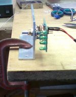
Iv'e done a bit of testing on the switch unit, I connected a voltage source to the power inputs of the switch module & then read the output pins that go to pin 6 & 8 on the BIII.
I expected to see the output pins vary from High to Low, I tested between the power ground & the output pins. The pins go low to ground but at no stage does a voltage show on the output pins, the reading I got went like this.
Input 1 No reading & No reading
Input 2 To Ground & No Reading
Input 3 No Reading & To Ground
Input 4 To Ground & To Ground
I haven't had a chance to test the BIII inputs
Attachments
- Status
- This old topic is closed. If you want to reopen this topic, contact a moderator using the "Report Post" button.
- Home
- More Vendors...
- Twisted Pear
- Buffalo III - flexibility without compromise.