
In my experiments, I found that the 10uF/50V capacitor had a strong influence on the sound. The only cap I liked in this position was the Nichicon ES bipolar, which expanded the depth of the soundstage and brought vocals forward. Bypassing with a 0.33uF Wima MKP10 may have brought out a little more detail on the high end, but the presentation was mostly set by the Nichicon ES.
Bypassing the ES with a Russian 0.5uF polystyrene made it worse and removed the three dimensionality. Using a 10uF polypropylene instead of the ES did the same thing.
This was all after the supply caps were upgraded to 1500uF Panasonic FM and 470uF caps upgraded to Nichicon KZ.
Bypassing the ES with a Russian 0.5uF polystyrene made it worse and removed the three dimensionality. Using a 10uF polypropylene instead of the ES did the same thing.
This was all after the supply caps were upgraded to 1500uF Panasonic FM and 470uF caps upgraded to Nichicon KZ.

Bon soir , Ciu
The gain is given by 1 + ( 1.5k/ 4.7K ), so in your case , you have a gain of ~ 1.3 .
For a gain of 6 you must change the 1.5 K resistor for 22 k.
Don't change the 4,7 K resistor , because it provide the DC bias condition of the input tube.
As the resistor is 5 times greater , the // capacitor must be ~ 5 times smaller for the same time constant...
Hope it help.
Yes, it helped me quite a bit.
I have a X-10D copy that I wanted to use as a preamp, so .98 gain was not an option. The 1.5K ohm resistors got replaced with 22K for the almost 6X (5.68) gain in your formula. Works very well! I tried replacing with 47K ohm resistors first, but there was a bit of distortion--too much gain...not enough feedback.
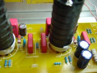
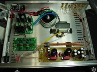
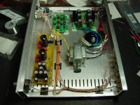
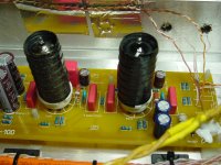
Some pics follow, I only had bigger 22K resistors as you see pictured. Also, there are British Mullards under the shields. Very nice performance.
Would advise anyone using this buffer in this form with a volume control, consider replacing these feedback resistors.
Also replaced the 10 uF / 50 V electrolytic caps with ELNA Silmic II. Someone said earlier that is was an improvement to do this.
Thanks for the tip.
Attachments
Last edited:
Hello Whaleman ,
I have questions about your upgrade . you say that to connect a potentiometer volume , in this buffer , must be replaced, the R from 1.5K to 22K .... but if I want to gain ? while if you do not want to gain ( 1 : 1 ) leave the values as they are , right? and connect only the volume control ?.
You can specify, if you want, the values of replaced components ( electrolyte capacitors , and film capacitors and other ... ??
Thanks for your kindness
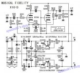
Referring to post #7 by coolmaster which contains circuit diagram.
I recognise the circuit in lower half as diode pump (walton cockroft full bridge rectifier) to generate higher +/- dc voltage supply, but what is the purpose of the two transistor circuit in each supply rail?
I recognise the circuit in lower half as diode pump (walton cockroft full bridge rectifier) to generate higher +/- dc voltage supply, but what is the purpose of the two transistor circuit in each supply rail?
Last edited:
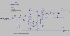
I've used the circuits posted earlier and traced through a Chinese clone of this as well as looked at boards (on ebay, some of which have errors!) but here is what I believe to the definitive circuit for the power supply i.e. the lower half;
Attachments
I,ll try to bulid this Buffer
An externally hosted image should be here but it was not working when we last tested it.
I've used the circuits posted earlier and traced through a Chinese clone <snip>
The grid and cathode seem almost at the same voltage in the second triode? Is that a correct way to bias the grid?
Does the feedback reduce the PS ripple/hum?
I am thinking of wiring this circuit using 6N3P tubes and using an external linear PS (+- 32 V).
You'll notice that also the starved plate voltage of only 5V (compared to 23V for 6n3p), the idea is to achieve very high gain, but also need to be driven (even into positive region) by low impedance source. There is about 30 db NFB so distortion is reduced to reasonable level. Sonic wise it may sound very good. For 6N3p you may need to starve plate voltage some more by increasing the plate load resistor, if it does not sound as good as ec88, I think.
Attachments
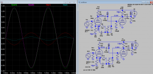
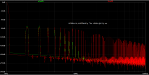
Using your sch, I step the value of cathode resistor and found least distortion at 40R for 6n3p. If you use 680R, you can bypass the cathode for more NF and damping. The distortion for 6n2p is lower at 0R, as compared to ecc88. Hence the harmonic pattern are also quite different, it maybe that this distortion pattern gives X10 the good sound, so I would suggest you use a tube adapter so you can hear both tube sound. You can attach here the 6n3p model you use for comparison if you like.
Using your model I got +8V also on the plate, the actual voltage across the tube (between plate and cathode) is about 40V.
It is 12.35V on the plate, 44v across the tube using the model I have here, so just 4V higher. Can verify with the original datasheet.
It is 12.35V on the plate, 44v across the tube using the model I have here, so just 4V higher. Can verify with the original datasheet.
Code:
.SUBCKT 6N3P 1 2 3 ; P G C (Triode) 16-Nov-2001
+ PARAMS: MU=31.33  EX=1.979  KG1=1920.5  KP=211.72
+ KVB=300.0  VCT=0.00 RGI=1k
+ CCG=2.5P  CGP=1.3P CCP=1.4P
E1 7 0 VALUE=
+{V(1,3)/KP*LN(1+EXP(KP*(1/MU+(V(2,3)+VCT)/SQRT(KVB+V(1,3)*V(1,3)))))}
RE1 7 0 1G
G1 1 3 VALUE={(PWR(V(7),EX)+PWRS(V(7),EX))/KG1}
RCP 1 3 1G    ; TO AVOID FLOATING NODES IN MU-FOLLOWER
C1 2 3 {CCG}  ; CATHODE-GRID;
C2 2 1 {CGP}  ; GRID-PLATE;
C3 1 3 {CCP}  ; CATHODE-PLATE;
D3 5 3 DX     ; FOR GRID CURRENT
R1 2 5 {RGI}  ; FOR GRID CURRENT
.MODEL DX D(IS=1N RS=1 CJO=10PF TT=1N)
.ENDS
Last edited:
Thanks Koonw for the analysis. At 40R, the 6N3P plate voltage stands at 8 V. I think I will have a 1K pot for the cathode resistor to play with both modes of operation.
Please review the attached 6N3P model.
The model you attached is more accurate than the model I have, thank you.
Attachments
- Home
- Amplifiers
- Tubes / Valves
- Musical Fidelity X10D schematic