yep! although mine was a copy, it wasn't very good even with many parts upgraded. All the PSU caps were changed to Panasonic FC and the caps in the audio path were mundorf supreme. I cant remember what valves I used. In any case, the decent components were removed and the rest of the board is still around somewhere. Either way its complete rubbish!!!
I had an original X10D and thought I would give it an upgrade by replacing the stock Jan ECC88's with some top flight Mullards. Result was horribly mushy with everything that is bad about valves.
The issue is that running ECC88's down at these voltages is highly suboptimal and so the circuit has to be specifically tuned to the characteristics of the valves supplied as stock. It is probably correct to say, that the original circuit can only sound good with stock ECC88' as supplied by MF.
You have been warned.
Shoog
X10-D general circuit suggestions.
I have just revamped my X10-D after it has been sitting idle for the past few years now seeing use on the end of my p.c external DAC. I was going to upgrade the valves but somewhere else someone suggested this was not the initial thing to do so I upgraded my X10-D with an capacitor upgrade kit first, if you want a sharper stock sound I recommend the JAN E88CC/6922, if you want a clearer or more accurate sound I recommend the coupling and PSU capacitor upgrade available elsewhere and can be easily searched for on the net and is also a diy based project for the price of about 2 economy valves if you care to look it up, there is also a 12vac@3A psu available from Maplins. I feel I can now utilize better quality valves (currently NOS Mullard sourced RTC E188CC's) without the original cheap and I mean cheap capacitors blurring the sound and therefore I can get a better idea of what the valves themselves sound like. If you like "nice muddle" that is the original X10D sound then stick with the original as the upgrade will remove the haze that I thought was the "valve sound"...it wasn't really, what you are left with is a more realistic sound with greater depth of sound and a "larger" midrange compared to the original despite the extra phono connection. IMHO.
Hope some or all of this helps. Cheers
It looks to me like X10-D is not an optimal tube buffer. It is highly constrained to work on an input power source providing 12VAC for simplicity and safety purposes. To be even reasonable it has to use an on-chassis double voltage doubler, giving an ultimate 48V DC from pseudo-ground to B+. That isn't enough for 6DJ8 or many others tubes to really shine, is it? Low distortion is achieved but not without rather large amount of feedback. Plus, the elaborate voltage doubling may be behind the loss of stereo separation at low frequencies (as measured by Stereophile), though you might still consider 55dB adequate at 100Hz, but what about 73dB at 500Hz?
A more optimal approach would either involve safety interlocking power system of some kind (or ignoring safety concerns? how safe is Audio Research SP10 power supply, does it use interlocking or just depend on non-foolish user?) or on-board transformer and power supply. A nice B+ would probably be in the vicinity of 200V, with lotsa current for 6dj8. Then you got real Toobes!
Robert Modjeski recommends 6DJ8 plate voltages 80-150V, so I'm guessing B+ should be about twice that.
http://www.tubeaudiostore.com/suitof6dfora.html
Meanwhile, I'm trying to figure what kind of B+ voltages the Yaqins use.
Last edited:
It looks to me like X10-D is not an optimal tube buffer. It is highly constrained to work on an input power source providing 12VAC for simplicity and safety purposes. To be even reasonable it has to use an on-chassis double voltage doubler, giving an ultimate 48V DC from pseudo-ground to B+. That isn't enough for 6DJ8 or many others tubes to really shine, is it? .
I'm sorry, but I think you are wrong !
The voltage B+ is not 48v, but symmetrical +- 34v , that's what I've measured on mine
R.C.
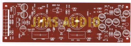
Hi guys, just finished assembling mine bought on ebay as printed circuit board with schematic and part list. While testing and measuring found with 12VAC as power supply the heaters on my EI ECC88 to be only 4.6V! I had the sound, but the heating volts were bothering me, so i raised the AC voltage to get the required 6.3V and ended up with 19.2VAC of power supply. The sound is nice and "wide" with voices and mids-to-hights up-front and noticeably less lows (connected to output of laptop and driving headphones - i've read somewhere that ecc88 has enough power to drive headphones and so i tried....worx nice - so i know i might get a different sound when connected to a power amp, but at the moment, in the middle of an ocean, this is the best i can do). I'm using Elna power caps, Solen coupling caps, Orange drop silver mica and UF4007 diodes.
Reading this forum i just found out that there should be +-30VDC supplied, and when i measure mine i read about 41 to 43VDC (due to increased PS volts). The tubes feel fine with that. But i honestly think that a better power supply for the heating should be done putting tube heaters in parallel and not in series due to a voltage drop on one valve (the difference is about 0.2 - 0.3V. And i think i'm going to do that. For the rest, for now i'm satisfied.
Reading this forum i just found out that there should be +-30VDC supplied, and when i measure mine i read about 41 to 43VDC (due to increased PS volts). The tubes feel fine with that. But i honestly think that a better power supply for the heating should be done putting tube heaters in parallel and not in series due to a voltage drop on one valve (the difference is about 0.2 - 0.3V. And i think i'm going to do that. For the rest, for now i'm satisfied.
Attachments
Hi Ciu,
What do you mean by "The output caps 2.2uf are also "wrong" ? On all schematics i've seen there's 2.2uF...
Regarding the 2 resistors R1 and R10, you mean they both should be 2.2ohm?
I'm gonna try the 2200uF modification...did you change the PSU caps as well to say 2200uF 50V (or 63V)?
What do you mean by "The output caps 2.2uf are also "wrong" ? On all schematics i've seen there's 2.2uF...
Regarding the 2 resistors R1 and R10, you mean they both should be 2.2ohm?
I'm gonna try the 2200uF modification...did you change the PSU caps as well to say 2200uF 50V (or 63V)?
Of course the C9 and C10 are enough to be 25V, but i was asking for C6, C7, C8 (specially the latter because it's very close to the + - 30V supply voltage).
Did you get about 2V difference when measuring the L and R channel PS voltage as well?
So you reckon i should try with R1 = 1200 Ohm?
Did you get about 2V difference when measuring the L and R channel PS voltage as well?
So you reckon i should try with R1 = 1200 Ohm?
Ok, i will wait then...well personally i think Elna are one of the best brands as well as being available almost anywhere and you don't have to sell any body parts to buy them. So far i have changed a few brands of caps (Nichicon, Elna, Vishay, Wima,...) and found out that russian PIO are cheap and super good, so i will try them as well.
How is the sound on your configuration? Enough bass? Any widening or 3D effect in yours?
How is the sound on your configuration? Enough bass? Any widening or 3D effect in yours?
Yes , Elna are among best caps, but I have lot of Panasonic FC, Vishay/BC .
Output caps , 2.2uf are changed to russian k73-16, 1.8uf each, 2 connected //
(eBay | 1.8uF 100V 5% tol. PETP CAPACITORS. K73-16. Box of 60)
Other caps, 0.22uf, are also K73-16, but 0.22uf, doesn't need bigger values.
I've choosed 6N23p-EV, as tubes replacement of 6dj8
About sound, something good, but not "heaven" !!!
I think ACF-2 from tubecad is better, 6n23p-ev , cascoded in cathode follower, with symetrical PSU +-85v, from 2x60v transformer.(http://www.tubecad.com/2012/02/07/ACF-2 9-Pin.pdf)
Hi I think it is strange to add a device after a device that does not sound too well just to color the sound and make it agreeable. Totally superfluous piece of gear. And yes, I have listened to them often. The owners made me listen to them as the X10D "improved" the sound quality ")
Better invest the money in a decent (tubed if you can't do without them) output stage so by omitting the opamp output stages. Shorter path, better results. I demonstrated this a few times with good response from the listeners. All X10D have been sold because of this and only the X pre stayed in some sets as it is a decent preamp.
Better invest the money in a decent (tubed if you can't do without them) output stage so by omitting the opamp output stages. Shorter path, better results. I demonstrated this a few times with good response from the listeners. All X10D have been sold because of this and only the X pre stayed in some sets as it is a decent preamp.
Last edited:
I just happen to have a K42Y-2, 0.22uF 500V here and i might give it a shot...regarding the 6N23P - already waiting ofr them (personally i've been always satisfied/happy with russian stuff being mil-spec (although normally bigger, but that is also why they sound great) and cheaper than any other items (that's why i'm using 6P14P in my RH84 and they sound excellent for half the money)...
I will check the ACF-2, and maybe make it become my next project..
I will check the ACF-2, and maybe make it become my next project..
B=+/-45V for baffer X10D
Hi guys!
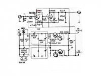
What changes are needed to the schematics for the tube buffer X10-D if you increase the anode power supply B = +/-45V (or B=+/-65V)?
See schematics:
Thanks for your help!
Hi guys!
What changes are needed to the schematics for the tube buffer X10-D if you increase the anode power supply B = +/-45V (or B=+/-65V)?
See schematics:
Thanks for your help!
Attachments
Last edited:
- Home
- Amplifiers
- Tubes / Valves
- Musical Fidelity X10D schematic