Hi everyone
I'm currently building an Aikido preamp (4X 6SN7) but I would like to have the possibility to switch between 6SN7 and 6AS7 output tubes.
Since 6AS7 is voltage limited compared to 6SN7, would it be a bad idea to use a 200VDC power supply for both topologies ?
Mr. Broskie suggests running 6SN7 @ 220-300V but I'd like to know if running 6SN7 at 200V would be catastrophic.
I plan to go on the "cheap" route at first with a simple RC power supply. (a 263CX 180-0-180, 250mA hammond transformer using only one side of the center-tap and 220ohms/220uF RC filter).
Anyone has tried ? Your ideas would be appreciated !
Thanks !
Thanks !
But is there any issues running a tube under the recommended value ?
It is simply a matter of a lower amplification factor ?
Also, is there anyone who used 6AS7 in their aikido ? I cannot find any recommended component values when using 6AS7 in M. Broskie's doc.
Thank you !
But is there any issues running a tube under the recommended value ?
It is simply a matter of a lower amplification factor ?
Also, is there anyone who used 6AS7 in their aikido ? I cannot find any recommended component values when using 6AS7 in M. Broskie's doc.
Thank you !
Another consideration, 6AS7's heater draws 2.5A va 0.6A of 6SN7.
You're right !
")
However, I'll recover a 8A, 6.3V transformer from a previous stereo double push-pull project which had 10 tubes to supply.
John Broskie has actually shown how to use a 6AS7.
http://www.tubecad.com/2005/July/blog0051.htm
From the link
The formula for the optimal ratio of power supply for the bottom tube is
Ratio = 1/mu + ½
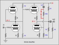
As you ca readily see, the greater the mu, the closer the ratio gets to 50%. But with a tube like the 6AS7, with a mu of 2, the needed ratio becomes ½ + ½ = 1 or 100%. Thus an Aikido amplifier with a 6AS7-based output stage should look like this:
Notice the missing voltage divider; all of the power supply is presented to the bottom triode’s grid.
http://www.tubecad.com/2005/July/blog0051.htm
From the link
The formula for the optimal ratio of power supply for the bottom tube is
Ratio = 1/mu + ½
As you ca readily see, the greater the mu, the closer the ratio gets to 50%. But with a tube like the 6AS7, with a mu of 2, the needed ratio becomes ½ + ½ = 1 or 100%. Thus an Aikido amplifier with a 6AS7-based output stage should look like this:
Notice the missing voltage divider; all of the power supply is presented to the bottom triode’s grid.
Hi Elkaid
If I undersood well you plan to use 200VDC for the B+. If yes... In an Aikido that implies in 100VDC (half the B+) across each tube. If you go for a B+ of 300VDC you will have 150VDC across each tube, a voltage that is better suited for the 6SN7. The 6AS7 is rated for V Anode max 250VDC, so you can safely run it with B+ of 300VDC, as there will be 150VDC across the tube.
Note that the 6AS7 will draw much more current than a 6SN7. Using CRC filters will make the voltage drop in the power supply increase, resulting in a different working point for the first 6SN7. It will work, but it will be different.
I hope this helps you
Erik
Thank you guys
You're right, I was referring to the voltage at the output of the power supply. Since the voltage seems to be "cut" in half, I'll be nowhere near tube's maximum voltage using 300VDC.
In that case, I presume the B+ isn't halved right ? If that's right, should I conclude that it would be a little more complicated than previously thought to be able to switch output tube without modifications ?
Thank you very much !
If I undersood well you plan to use 200VDC for the B+.
You're right, I was referring to the voltage at the output of the power supply. Since the voltage seems to be "cut" in half, I'll be nowhere near tube's maximum voltage using 300VDC.
Notice the missing voltage divider; all of the power supply is presented to the bottom triode’s grid.
In that case, I presume the B+ isn't halved right ? If that's right, should I conclude that it would be a little more complicated than previously thought to be able to switch output tube without modifications ?
Thank you very much !
Hi Elkaid
The voltage divider Bas refers to is only passing AC noise present at the power supply. See that it 'starts' with a cap, which blocks DC, but allows flow of any AC. This AC (the B+ noise) is than reduced thorugh the voltage divider...and fed to the grid of the triode.
You can make a voltage divider that is ideal for the 6SN7, and place a jumper or swith across the upper resistor. With jumper/ switch closed the circuit works for the 6AS7, with it open it works for the 6SN7. Should not be much of a hassle, as you can change the setting while you are changing the tube
Hope this helps
Erik
Attachments
Are you planning to use the 6AS7 as input and output or what?
Your switch bypassing R15 should do the job there. I haven't done the math yet but I don't think your cathode resistor values are going to keep in the proper operating point for a 6SN7.
What about the difference in current draw between the 6SN7 and 6AS7? Don't you need about 50mA for the 6AS7 and 5-8 for the 6SN7? How are you going to change the B+?
You're probably right.
6AS7 as output only keeping 6SN7 as input.
You may be right.
From Erik :
Would the voltage drop be significant ?
Does using a choke filtered supply would be better suited ?
Thanks for your input !
Are you planning to use the 6AS7 as input and output or what?
6AS7 as output only keeping 6SN7 as input.
What about the difference in current draw between the 6SN7 and 6AS7? Don't you need about 50mA for the 6AS7 and 5-8 for the 6SN7? How are you going to change the B+?
You may be right.
From Erik :
Note that the 6AS7 will draw much more current than a 6SN7. Using CRC filters will make the voltage drop in the power supply increase, resulting in a different working point for the first 6SN7. It will work, but it will be different.
Would the voltage drop be significant ?
Does using a choke filtered supply would be better suited ?
Thanks for your input !
The (extra) voltage drop in the PS when using the 6AS7 will be the extra current drawn multiplied by the resistance in the PS (V=I*R).
As you mention, a choke would reduce the drop, as its DC resistance is less for the same amount of accomplished filtering. You could also use a (series) regulator, which would yield constant B+ whatever current you draw - but adds somewhat in complexity, although a Maida is simple and cheap.
Burnedfingers is right about the biasing resistors, you should check if the same value of resistor can be used to bias both the 6SN7 and the 6AS7...you couls also add a parallel resistor, which can be turned on/off with a switch, but that also adds in complexity...
Erik
Hi !
Thanks for your replies guys.
For now, I gave up on the "dual personality" feature and decided to focus on 6SN7 only Aikido with a B+ of 300VDC.
Right now, I've got a Hammond 269GX transformer (225-0-225, 65mA) that I would like to use. Is 65mA enough for the 6SN7 Aikido ? The only datasheet that I've found is in German and I'm not too sure whether I should look for cahode or anode current or any other parameter when estimating PS requirements.
Well, assuming that I could use my 269GX transformer, I came up with the following schematic. Your comments would be very appreciated.
Thanks and have a nice day !
Attachments
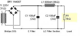
If you want to simulate the power supply, it's best to estimate the current draw for your preamp and plug that in to PSUD as a current source. It'll give you a more accurate picture. When you get your transformer, you can actually measure the unloaded voltage, and the primary and secondary resistances. If you enter that into the transformer data, and you have the series resistance of your choke, you will get very close to the real values.
You can estimate the current through the tube by looking at the data sheets for the plate curves. Pick the current you want and the plate voltage (remember it will be half the B+, as you have on section stacked on the other), and from the curves, estimate the negative grid voltage at that point. Don't worry if you have to extrapolate between grid voltages. It not going to be exact anyway. Then pick your cathode resistor to give that voltage drop at your chosen current.
BTW, the plate current and cathode current will be the same in these applications, as you will have no significant grid current.
Sheldon
Edit: This table will give you some typical values: http://www.tubecad.com/2006/05/blog0064.htm
I attached a schematic for a Aikido 6SN7 amplifier.
Elkaid
The 6sn7 and 12sn7 are the same except for the heater voltage.
You may want to plug in the current needs into the power supply software to size your circuit correctly. I used this Aikido circuit with 6SN7's and it sounds quite nice.
You may want to look at the Aikido thread where Bas outlines a typical Aikido power supply. If you follow this closely you will end up with an error proof power supply. You probably will have to scale your voltage dropping resistors to obtain the correct final B+ voltage.
Attachments
Thanks !
I read in Mr. Broskie's doc that he recommends to drive the output tubes "hotter" than input tubes. Your schematic seems to confirm that (5mA for input tube vs 10mA for output tubes).
Sorry to get down to the basics but... Since 6SN7 is a dual triode, is the 5mA and 10mA values are rated for the 6SN7 tube or for ½6SN7 ?
Ultimately, when calculating power requirements, should I add current values this way :
(5mA * 2 6SN7 Input Tubes) + (10mA * 2 6SN7 Output Tubes)
or that way :
(5mA * 4 ½6SN7 Input Tubes) + (10mA * 4 ½6SN7 Output Tubes) ?
Thank you very much !
For looking at operating points, plate curves, etc., you treat each triode as if it were a separate entity. Of course, stacked triodes must see the same current, whether single triodes or both in the same tube. The current through each stacked section is the same as for the whole tube, since they are connected in series. The current rating for the 6SN7 is about 20Ma, (each or both sections, no matter).
However, since the two triodes are in the same envelope in this case, you have make sure that their combined dissipation doesn't exceed the max. rating for the tube as a whole. The 6SN7 is rated at 5 watts for a section, but because you have two sections in the same tube they cannot both be run to the max at the same time. The total combined power cannot exceed 7.5 watts, or the tube will overheat.
In your example, a preamp with 5Ma in the first position and 10Ma in the second, would have a current draw of 15Ma/channel or 30Ma total.
I think the suggestion for running the second position "hotter" is only indirectly related to heat. The main point is to run a generous amount of current in the second position. The extra current helps to drive any capacitance in the following path and it means a smaller cathode resistor, which gives a lower Z-out.
Sheldon
Thank you very much, I'm beginning to understand a little more of what's going on in those tubes
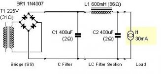
Also, according to your suggestion Sheldon, I modified my PS simulation a little and added current.
With the following schematic, I get around 306VDC with 5mV ripple.
I suppose it shouldn't be that bad. Or is there a simple way to flatten ripple even more ?
Thanks again for your help everyone, it's very appreciated
Attachments
Elkaid said:With the following schematic, I get around 306VDC with 5mV ripple.
I suppose it shouldn't be that bad. Or is there a simple way to flatten ripple even more ?
Thanks again for your help everyone, it's very appreciated
I think that level of ripple would be fine. Remember, one of the big virtues of the Aikido is excellent power supply ripple rejection - PSRR.
But, even if you stay with that, by all means play with PSUD. It costs nothing but your time and you can get a feel for what the relative magnitude of effectiveness for various changes will be. Try adding an RC section, for instance - say a 500R resistor and a 100uf cap, or? Play a little.
Sheldon
edit: BTW, that input cap is pretty big. You can get equal or better performance with a smaller input cap an a bigger choke. Try 5uf or so and a 25H choke.
- Status
- This old topic is closed. If you want to reopen this topic, contact a moderator using the "Report Post" button.
- Home
- Amplifiers
- Tubes / Valves
- Aikido with dual personality