Hi !
Thank you, you were right, adding a RC section made a noticeable difference ! Ripple have lowered even more. (Around 2mV).
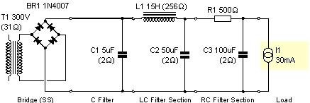
The RC values you mention seems to be right on target. I found a choke from Hammond which gave nice results but I needed to lower a bit the L value (15H) from the 25H suggested.
Beside that, if my calculation are correct, the resistor will need to dissipate something like 30watts with a big rush during 200ms on power up so I'll probably go for something like 50watt resisor depending on size.
Thanks gain and I'll keep you informed about the project progression.
Have a nice day !
Thank you, you were right, adding a RC section made a noticeable difference ! Ripple have lowered even more. (Around 2mV).
The RC values you mention seems to be right on target. I found a choke from Hammond which gave nice results but I needed to lower a bit the L value (15H) from the 25H suggested.
Beside that, if my calculation are correct, the resistor will need to dissipate something like 30watts with a big rush during 200ms on power up so I'll probably go for something like 50watt resisor depending on size.
Thanks gain and I'll keep you informed about the project progression.
Have a nice day !
Attachments
Elkaid said:I found a choke from Hammond which gave nice results but I needed to lower a bit the L value (15H) from the 25H suggested.
Beside that, if my calculation are correct, the resistor will need to dissipate something like 30watts with a big rush during 200ms on power up so I'll probably go for something like 50watt resisor depending on size.
That looks fine. The 25H was just a ballpark guess. You don't need to worry too much about the short inrush current for the resistor. The ratings are determined for steady state conditions. It won't heat up fast enough with a brief inrush to matter. The 500R resistor will dissipate about 1/2 watt at a steady state. A 5 watt there will be more than adequate. You can use larger, but there is no benefit.
Sheldon
Hello everyone again !
I was playing with PSU Designer lately and came up with the following power supply.
I have never built tube-based power supplies and your comments would be very appreciated (again !)
Btw, is that normal that the software returns an error message box if I increase C1 to let's say 10uF ? I'm asking because my current value (4-5uF) is relatively close to 10uF.
Regards,
Emmanuel
Attachments
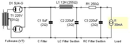
What's the message say? I did a quick check and didn't get an error. You should be well within any limits with that supply. You can even increase the input cap to at least 40uf. Just check the data sheet and calculate the plate supply impedance (formula is on the data sheets) and make sure it is enough, or add series resistance before the cap if needed.
Sheldop
Sheldop
Hi and thanks Sheldon and Erik ")
You're right, it's a spike lasting 0,0000000000000001 second dropping rapidly right at the power-up (0.00 sec)
(well, it's a bit longer than that, but let's say that the current is over rectifier specs during 100-200 ms max)
Thank you, you're right
Well, my error sorry, I was getting the message with the schematic I posted but with a single rectifier tube. (I added the second rectifier tube to get rid of the error message)
Can I conclude that if I get this message during the first second following power-up I can "ignore" it ?
Thank you guys, I'm really beginning to like this software
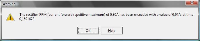
Here's a screenshot of the error
I assume the error is within the first second of the simulation? something like a high spike on the graph?!
You're right, it's a spike lasting 0,0000000000000001 second dropping rapidly right at the power-up (0.00 sec)
(well, it's a bit longer than that, but let's say that the current is over rectifier specs during 100-200 ms max)
What's the message say? I did a quick check and didn't get an error.
Thank you, you're right
Well, my error sorry, I was getting the message with the schematic I posted but with a single rectifier tube. (I added the second rectifier tube to get rid of the error message)
Can I conclude that if I get this message during the first second following power-up I can "ignore" it ?
Thank you guys, I'm really beginning to like this software
Here's a screenshot of the error
Attachments
Elkaid said:Well, my error sorry, I was getting the message with the schematic I posted but with a single rectifier tube. (I added the second rectifier tube to get rid of the error message)
Can I conclude that if I get this message during the first second following power-up I can "ignore" it ?
I think Erik hit it.
I'm curious; when you say you did it first with a single tube, do you mean you simulated it with a half wave rectifier, using only one diode? The full wave rectifier you show would be the typical usage.
Yes, you can safely ignore it. As Erik said, that spike will not occur during normal operation because the filament heats up gradually. The closest you would come is to shut the supply off long enough to drain the cap, then turn it back on before the filament has cooled too much - don't even know if you could do it under your load conditions and reservior sizes.
BTW, if you look under options, there is a slow start option that I believe will simulate a filament warm up. Haven't checked the actual slope.
Sheldon
Thank you guys, it's always a pleasure
Yes, my first design was half-wave using a single rectifier tube. I added a second rectifier (full wave) to get rid of the error message. I thought that I was doing something wrong in my design.
Later, when playing with different values, I observed that I had less ripple when using 2 rectifiers so I kept the full wave architecture without asking myself too much questions.
Thanks ! You're right, the error doesn't show up when enabling soft-start option.
I think I'll keep the full wave approach to increase the voltage without changing transformer and to get less ripple.
Also, adding a second rectifier isn't a bad thing aesthetically. (Beside the horrible 5V 3A filament).
BTW, thanks to you guys. Now that I'm more comfortable with PSU Designer, I can now resume previous projects put aside because of power supplies related issues (such as hard to find transformers etc).
Also, I managed to decrease ripple even more with the following schematic (now ¼mV):
Best regards,
Emmanuel
I'm curious; when you say you did it first with a single tube, do you mean you simulated it with a half wave rectifier
Yes, my first design was half-wave using a single rectifier tube. I added a second rectifier (full wave) to get rid of the error message. I thought that I was doing something wrong in my design.
Later, when playing with different values, I observed that I had less ripple when using 2 rectifiers so I kept the full wave architecture without asking myself too much questions.
BTW, if you look under options, there is a slow start option that I believe will simulate a filament warm up. Haven't checked the actual slope.
Thanks ! You're right, the error doesn't show up when enabling soft-start option.
I think I'll keep the full wave approach to increase the voltage without changing transformer and to get less ripple.
Also, adding a second rectifier isn't a bad thing aesthetically. (Beside the horrible 5V 3A filament).
BTW, thanks to you guys. Now that I'm more comfortable with PSU Designer, I can now resume previous projects put aside because of power supplies related issues (such as hard to find transformers etc).
Also, I managed to decrease ripple even more with the following schematic (now ¼mV):
Best regards,
Emmanuel
Attachments
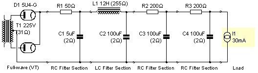
Elkaid said:Also, I managed to decrease ripple even more with the following schematic (now ¼mV):
I would think that something along the lines of your previous model would be more than adequate for an Aikido line stage. One of the key features of the Aikido is outstanding PSRR, or noise rejection. I think you are well into the territory of diminishing returns with the latest version. But by all means, model away.
Sheldon
Elkaid said:s, my first design was half-wave using a single rectifier tube. I added a second rectifier (full wave) to get rid of the error message.
You didn't actually add a second tube, you just used both plates of the rectifier. I think the convention is to call diode tubes with two plates a rectifier - meant to be used as a full wave rectifier (you could, of course, parallel the plate outputs to form a single diode). Diode tubes with a single plate are simple called diodes, as in diode damper tubes. If I'm not mistaken, the 5U4-G is a rectifier (single cathode, dual plates).
Sheldon
Oh, and with your fairly low voltages and current requirements, model a smaller rectifier, such as a 6X4 or 12X4.
Hi Sheldon,
Oh my... I was about to install a second 5U4G Tube....
Well, I wanted to see how far I could get with ripple eliminitation.
Thanks a lot
Oh my... I was about to install a second 5U4G Tube....
But by all means, model away.
One of the key features of the Aikido is outstanding PSRR, or noise rejection
Well, I wanted to see how far I could get with ripple eliminitation.
Thanks a lot
Hi everyone,
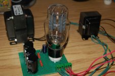
I just finished the prototype of my first power supply using tube rectifier and I thought some of you might be interested in some pictures so here they are :
(Here's the schematic ) I get around 350Volts wihtout load but should go down around 260Volts once the aikido connected.
I just finished the prototype of my first power supply using tube rectifier and I thought some of you might be interested in some pictures so here they are :
(Here's the schematic ) I get around 350Volts wihtout load but should go down around 260Volts once the aikido connected.
Attachments
Hi everyone,
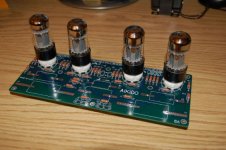
Since my project is almost completed (chassis not completed yet), here's my results.
As many diyers here, I experienced 60Hz hum. It wasn't that much but enough to make me wondering. I knew that I could do better.
I was using "cheap" Electro Harmonix 6SN7 for both input & output tubes and AC heater. I tried "grounding" filament supply but also referencing filament supply to ¼B+ without any success.
The only solution left was to use DC filament supply. I made a quick experiment using unregulated DC filament supply and "grounding" it through a 0.1uF cap. All of a sudden, the hum disappeared. The Aikido is now dead quiet.
Well, right now, I'm putting my efforts in completing the chassis.
I hope this will help anyone interested in Aikido building.
(As a side note, I stated in a previous post that my with B+ power supply schematic, I was expecting around 260VDC once load connected. I'm not sure what I've done wrong in PSU Designer II but during my tests, I measured 292VDC. IMO, it's better than I orginally expected but I hate that kind of suprises)
Regards
Since the 269GX & 167Q5 are both center tapped, (first confirm this is safe when using a separate HV and Filament transformer) try wiring your PS like this http://www.emissionlabs.com/datasheets/274.gif
Max
Max
- Status
- This old topic is closed. If you want to reopen this topic, contact a moderator using the "Report Post" button.
- Home
- Amplifiers
- Tubes / Valves
- Aikido with dual personality