Ideally, a parafeed transformer should be wound on a gapless high permeability toroid core, which will allow a combination of highest primary inductance, lowest parasitics, and lowest distortion. Such cores suitable for SE 2A3 are available from Magnetics or Vacuumschmelze for a cost of about $100 apiece.
A suitable transformer may be a 25 VA power toroid with 220 V primary and 8-12V secondary (depending on your speaker impedance). Look at offerings from Antek, their transformers have primary inductance of 40-50 H, and they have high frequency response beyond 20 kHz. Antek also makes purpose tube OPT toroids, but they are 7-8 k primary.
A suitable transformer may be a 25 VA power toroid with 220 V primary and 8-12V secondary (depending on your speaker impedance). Look at offerings from Antek, their transformers have primary inductance of 40-50 H, and they have high frequency response beyond 20 kHz. Antek also makes purpose tube OPT toroids, but they are 7-8 k primary.
sser2,
What can you tell me about your experiences using toroid cores for parafeed output? Benefits, concerns?
I did a search for Magnetics and Vacuumschmelze. I am not sure which Magnetics you are referring too. Regardless, I am not ready to wind my own.
I also looked at the Antek size you mentioned and I am not sure if I am looking at the right thing. They were very cheap.
I appreciate your help, but I need a little more help.
thanks,
ToddD:
Winding your toroid is pretty easy job, so you may reconsider.
Advantages of toroid are many. First, you fully utilize the highest core permeability, meaning much less wire turns for the same inductance, as compared to other core types. Second, high permeability cores are wound with very thin tape (1 mil or less), so full high permeability is retained at 20 kHz and beyond, whereas permeability of conventional steel cores collapses below 1 kHz. Third, because of much lower number of turns required for the same inductance, winding capacitance and leakage inductance are much lower than in conventional transformers, so no sophisticated winding schemes are necessary. Fourth, longer coil is conducive to lower leakage inductance.
The only drawback of toroid is intolerance to even slight DC magnetization. But it doesn't matter in parafeed, you have all advantages and no disadvantages.
In Mouser catalog, search "Vitroperm". You need catalog # T60006-L2090-W518. It is 90x60x20 toroid. 3K primary is 800 turns of 34 AWG, and 4 Ohm secondary 30 turns of 16 AWG. Very easy winding job, all you have to care of is spreading windings evenly around the core. Primary inductance is about 50 H. For your money and effort, you will have the best parafeed transformer in the world.
I will provide link to Antek transformer in a separate post.
Antek transformer:
Look on eBay for Antek transformer. The one you need is AN-0307, 2x115 primary and 2x7 secondary. Connect primaries in series for 3K; parallel secondaries is 4 Ohm out and series secondaries 16 Ohm out.
Yes, it is cheap. Even more incentive to try. Cheap but good.
Look on eBay for Antek transformer. The one you need is AN-0307, 2x115 primary and 2x7 secondary. Connect primaries in series for 3K; parallel secondaries is 4 Ohm out and series secondaries 16 Ohm out.
Yes, it is cheap. Even more incentive to try. Cheap but good.
Years ago, I used a couple of Anteks in a 6V6 parafeed amp. They worked very well, but I noticed that a period of break in was needed before the sound focused. The amp was a hodgepodge of different ideas but was a lot of fun to build. It's one of the few I have not disassembled.
Audio ratbag: Lumiere
Another alternative are line transformers. I used the cheap Radio Shack versions for years. They were very small so no great bass, but they are much better than you would expect at higher frequencies. There were rumours that some of the lams were nickel.
ray
Audio ratbag: Lumiere
Another alternative are line transformers. I used the cheap Radio Shack versions for years. They were very small so no great bass, but they are much better than you would expect at higher frequencies. There were rumours that some of the lams were nickel.
ray
Oh, forgot about my experience. I didn't try parafeed, I don't want capacitors in the signal path. But I tried Antek transformer in push-pull 2A3, and it worked very well. To my surprise, it even tolerated a few milliamps of DC imbalance. Balance adjustment was needed though from time to time.
sser2,
No capacitors in your signal path?
Really.
What power source are you using?
Batteries?
DC Generator?
Solar Cell Array?
Thermocouple array?
A regulator IC? . . . (Oh, it is fed by capacitors)
Or what?
Do you have capacitors across the B+.
The signal current is drawn from those capacitors.
Is that current part of the signal path?
How about a reading of Kirchoff's law.
IRMC (I Rest My Case).
sser2,
You have me interested in winding my own OPT. I will have to look and see what I can find on winding. I will most likely buy complete OPTs first and then look at winding one later for comparison. I need to review the Antek information.
ratbagp,
I have read your blog postings on your resistive loaded parafeed amps for the 6C33C and the 829B. Are those still assembled?
I am considering using resistive loading with a 6336A. It has a rp of 200. I know resistive loading is inefficient, but so are SET's.
thanks
I recently moved to Australia from the USA and in the process disassembled most of my amps including the 829B and 6C33C amps. I may reassemble them but there are other amps I plan to build first. My new location is warm to hot most of the year (think Key West) so dealing with the heat generated by the resistive load is a problem, particularly with the 6C33C. When I disassembled the 6C33C amp I discovered that some of the plywood under the 1K 100 watt resistors had started to char.
Anyhow, why not try it out in breadboard style. See if you like it.
Incidentally, you might find the following link interesting. It goes into parafeed and the interaction between the power supply and the signal path.
The Audio Signal Path; Minimising Power Supply Interaction | Richard Sears, Vacuum Tube Audio
ray
The signal is generated from the power supply, therefore the power supply cannot be "isolated" from the active device path which should preferably consist of one (1) active device and resistors. Transformers should not be exposed to DC voltage but the position of the DC blocking capacitor makes no difference. The harmful impact of the rectifiers was not addressed. So what was achieved?
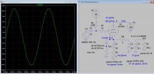
....Smaller transformers have more primary inductance. These are all for 230 V primaries.
25 VA: 160 H
50 VA: 85 H
100 VA: 40 H
200 VA: 12 H
For same voltage, higher power is higher current and lower impedance.
25 VA, 0.11A, 2k,: 160 H = 30Hz
50 VA, 0.22A, 1k,: 85 H = 32Hz
100 VA 0.44A, 500r,: 40 H = 30Hz
200 VA 0.88A, 250r,: 12 H = 18Hz
Parafeed output transformers have no better core material, but make use of the situation that one coil (the anode choke) has to manage the current flow and another (the parafeed) has only to deal with the "better" signal without the idle current. This enables for a smaller transformer design without any core gap. Its like a single ended transformer, without the core gap for the idle current. Or you can use a PP- design and wire it single ended, because they miss the idle current gap by design. Not every PP- design is able to deliver high quality and bandwith, but many can be used parafeed, too.
- Status
- This old topic is closed. If you want to reopen this topic, contact a moderator using the "Report Post" button.
- Home
- Amplifiers
- Tubes / Valves
- Drawbacks of Parafeed?