Yes you cann't go wrong that the price if you want something to modify and tweak.
With mine I changed the coupling caps but didn't really notice much change.
I then altered the driver valve connections to enable me to use the ECC*** range.More readilly available here in the UK and I've got a shed load of them.
This means cutting the PCB tracks and soldering some links.
I,ve not really come to any firm conclusions as to which ECC is best.
I also slightly lowered the feedback.
If your incoming mains voltage is high you might find heater voltages are a bit high.
I,ve tried various output valves ie. Mullard,TFK and Brimar thinkI can safely say that there is not a lot wrong with the suppied Sovteks.
I also have the Yarland FV 34A which is an SE design using 2 EL34's driven by 5670's.
With this amp I triode connected and removed feeback altogether
As the amp has fixed bias I can treak it within reason for a load of different octal fit valves. I've used 6L6,KT66,EL37,NR77 plus a few other obscure CV marked valves. It has a massive power TX and runs cool all day.
To be quite honest it sounds so good I won't be bothering to make any further changes and all this for £180 delivered.
STU
Here is my promised diagram for the EL84 amp:
(there may be errors!)
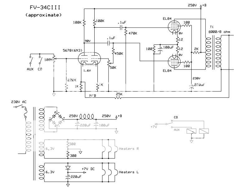
- The input stage is a classic (old fashioned) paraphase. It requires adjustment for AC balance when changing tubes. It could be fun to try to use the adjustment to tune the harmonic distortion spectrum with an analyser.
- The output stage is pentode mode. The slightly lower than normal common cathode resistor explains the claimed class-A operation.
- The OPT unfortunately lacks UP taps. It will therefore only allow penthode mode, as supplied, with 10W, or rewiring the 100ohm resistors for triode mode which gives around 3W.
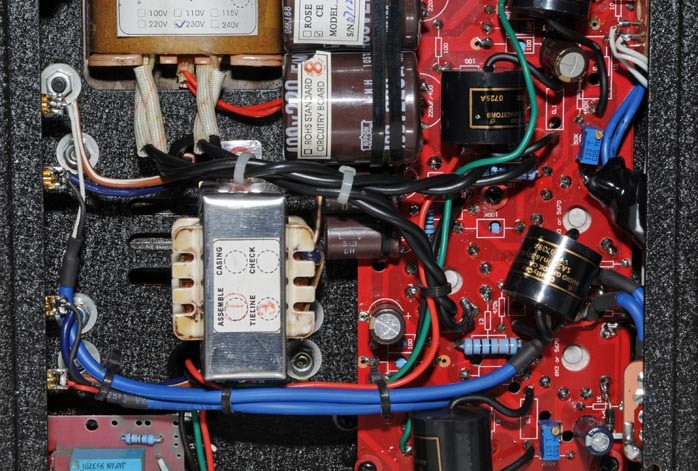
- The OPT appears to be fairly decdent. Probably around 1.5 Kg each. Oscilloscope view of square waves look exemplary. HF roll-off start at around 50KHz. My measurements indicate that the primary impedance may be slightly less than the common 8K. The optimum speaker impedance should therefore probably not be much below 8 ohm. (Photo of OPTs]
- The NFB is only around 4dB. Measured output impedance in pentode mode is 5 ohm, and 5 ohm in triode mode. Both with NFB. Triode mode without NFB is 7 ohm.
I have rolled theh tubes with GE 5670 and JJ EL84, and just managed to squeeze in Russian PIO coupling caps. Would probably ditch the circuit board and install new tube sockets for more extensive modifications (re-build).
The sound is decent. Not as sweet and airy as my vintage SE amp, but more bass punch.")
Svein.
(there may be errors!)
- The input stage is a classic (old fashioned) paraphase. It requires adjustment for AC balance when changing tubes. It could be fun to try to use the adjustment to tune the harmonic distortion spectrum with an analyser.
- The output stage is pentode mode. The slightly lower than normal common cathode resistor explains the claimed class-A operation.
- The OPT unfortunately lacks UP taps. It will therefore only allow penthode mode, as supplied, with 10W, or rewiring the 100ohm resistors for triode mode which gives around 3W.
- The OPT appears to be fairly decdent. Probably around 1.5 Kg each. Oscilloscope view of square waves look exemplary. HF roll-off start at around 50KHz. My measurements indicate that the primary impedance may be slightly less than the common 8K. The optimum speaker impedance should therefore probably not be much below 8 ohm. (Photo of OPTs]
- The NFB is only around 4dB. Measured output impedance in pentode mode is 5 ohm, and 5 ohm in triode mode. Both with NFB. Triode mode without NFB is 7 ohm.
I have rolled theh tubes with GE 5670 and JJ EL84, and just managed to squeeze in Russian PIO coupling caps. Would probably ditch the circuit board and install new tube sockets for more extensive modifications (re-build).
The sound is decent. Not as sweet and airy as my vintage SE amp, but more bass punch.
Svein.
I also own a FV-34C III....mine has arrived with Shuguang EL84 tubes and not Sovteks....anyway, a very good sounding little amplifier....better than most solid state integrated at the same price....I found it to be very natural sounding...sweet, very detailed...very well integrated in my system with NAD C521BEE and B&W DM601 S3....
for Svein: I'm planning to change the Shuguang EL84 with JJ or TAD.....I'm assuming that no bias settings can be made....can you please describe the procedure to set the AC balance? Do I need to set those two little screws between the tubes? Any particular tools are needed to set that balance? Many thanks.
for Svein: I'm planning to change the Shuguang EL84 with JJ or TAD.....I'm assuming that no bias settings can be made....can you please describe the procedure to set the AC balance? Do I need to set those two little screws between the tubes? Any particular tools are needed to set that balance? Many thanks.
Attachments
The AC balance of the paraphase phase splitter only need adjustment if you change the driver tubes.
For adjustment, feed a stable AC signal to the amp from a test CD or a signal generator. Adjust the small trimmer pots to get equal level of AC on both of the 0.1uF caps. Measure with a multimeter set to AC reading. The level will be a few volt of AC,
but be careful, THERE WILL BE HIGH DC VOLTAGE !
Even without adjustment there is no risk of any harm, but the driver signal to both tubes may be unequal, and some loss of power.
Space inside this little amp is a little small for experimentation, but I have managed to play with different phase splitter configurations, feedback, penthode and triode mode, and Russian PIO coupling caps.
SveinB
Member
Joined 2004
An externally hosted image should be here but it was not working when we last tested it.
Hi
I sell these amps with Shuguang EL84 tubes and Beijing 6N3 tubes. I tried JJ EL 84, this degraded the sound. The JJ's sound harsh in this amplifier. In other amplifiers the JJ tubes work pretty good. Just not in this one.
A little off topic. I visited the old Yarland factory (they moved to a new factory in may 2007).
The factory visit photo's can be found here: (text in Dutch)
Yarland factory visit
Kind regards
Roland Breteler
Member
Joined 2004
Hi,
I cannot fix your skreekie problem form behind my computer screen. Please contact the dealer you bought the Yarland from. He should help you fix the problem.
About the bias, yes sure that can be done. If you do not know yourself how to do this, please contact a good tube repair shop.
Sorry, no easy fixes for both problems
Kind regards
Roland
(Yarland EU)
Member
Joined 2004
Hi,
First English Yarland FV34CIIISA review on sixmoons:
Full review:
Sixmoons FV34CIIISA review
First English Yarland FV34CIIISA review on sixmoons:
The Yarland FV CIII SA is great way to get into tubes for just about anyone. A very affordable price tags to a sweet looking and very well-performing push/pull EL84 amplifier. And it is that typical EL84 sound that made the sound of the 50s what it was (read Jeff Day's intro on this tube here). It is this nostalgic feat that makes the FV 34 also a great addition to the amp inventory of hard-weathered audiophiles - and tube rolling is allowed. Full steam ahead.
Full review:
Sixmoons FV34CIIISA review
The AC balance of the paraphase phase splitter only need adjustment if you change the driver tubes.
For adjustment, feed a stable AC signal to the amp from a test CD or a signal generator. Adjust the small trimmer pots to get equal level of AC on both of the 0.1uF caps. Measure with a multimeter set to AC reading. The level will be a few volt of AC,
but be careful, THERE WILL BE HIGH DC VOLTAGE !
Even without adjustment there is no risk of any harm, but the driver signal to both tubes may be unequal, and some loss of power.
Space inside this little amp is a little small for experimentation, but I have managed to play with different phase splitter configurations, feedback, penthode and triode mode, and Russian PIO coupling caps.
SveinB
Svein,
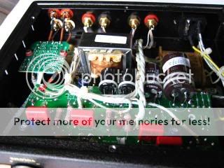
Any chance you could post a pic of the inside showing where exactly to place the probes to measure the AC balance.


It looks like you found the caps; the big black cylinders across the PCB.
One side of each cap is connected to the driver anode with about 150V DC on it, the other end at the EL84 grid at 0V DC potential. You can measure the AC signal on either side of the caps.
Be sure to use a multimeter with a reasonably high input impedance (preferably 1 Mohm). If the impedance is low you will load the driver and measure lover voltage than the actual.
If you are not comfortable poking around inside the amp, adjustment is not critical if you use the same type tubes as before. A little AC unbalance only reduces the max power a little, and increases 2'nd harmonics which could be "ear-friendly".
SB
- Home
- Amplifiers
- Tubes / Valves
- Yarland 34 ciii amp