Svein, thanks for the help.
I finally got to measuring AC balance and was able to find for each channel at least one JAN 5670 and one 6N3P-EV that can replace each other with no rebalancing. I often switch between Ei and Telam power tubes and for some strange reason Ei's go well with 5670's and Telams with Russian drivers.
Credit to Yarland - everything was set fine for the original Chinese 6N3 the amp was shipped with (which also sounded decent and remain as spares)
- The NFB is only around 4dB. Measured output impedance in pentode mode is 5 ohm, and 5 ohm in triode mode. Both with NFB. Triode mode without NFB is 7 ohm.
Svein.
I just realized my normal listening level puts out just over 1V, amounting to 0.125 W into 8Ohm so may as well try triode strapping as I'm not likely to go over 2W (96dB speakers) very often.
Svein, would you be kind to point out which resistors from the drawing would need to be rewired/removed and/or new ones added? Hopefully it can all work out without track cutting (but not the end of the world if some need to go).
Also, if putting an extra switch for B+ (to delay while filaments warm up) what would be be the best place for it - on PT AC secondary, after rectification, after the choke?
kuly,
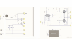
If there are 2 schematics, perhaps there were 2 different production versions.
Are you looking to build your own version or essential copy of that amplifier, using your own parts?
Or, do you have one of the actual production amplifiers?
Thanks!
This is separate from your question, both those schematics use Paraphase splitters.
All kinds of phase splitters have one or more tradeoffs.
I tried Paraphase splitters. I am not a fan of any of the various versions of Paraphase splitters.
I also tried concertina phase splitters. I am not a fan of concertina phase splitters.
Just my opinions
I like Long Tailed Pair phase splitters (LTP). I use various constant current sinks (CCS), including LM334.
Just another of my opinions
Last edited:
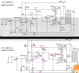
Just my opinion, the top schematic is my preference.
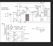
Perhaps the most difficult thing for either schematic is to adjust the negative feedback resistor values, and possible lead capacitor, to work with the model of the output transformer you are going to use.
And, notice that the output transformers are 8k Ohms plate to plate on the top schematic, and 6500 Ohms plate to plate on the bottom schematic.
I do not really like that 50k Pot. If the wiper does not make contact, that will cause trouble.
But the solution on the top schematic is simple. Just connect the 50k pot wiper to the un-connected end of that pot.
Just another reason for me to prefer the top schematic.
I also like the idea of 8k Ohms plate to plate.
Can some of you more knowledgeable readers take a look and tell us which of the 2 schematics you prefer.
Notice: I do not use any global negative feedback in any of my amplifiers. But my amplifier topologies are different in many other ways than what is in the 2 schematics above.
Last edited:

Kuly,
Yes,
The modification to schematic # 1 should work without any resistance changes as long as the input stages gains are 10 or more.
With the wiper connected to the end of the pot, even if wiper is not making a good contact to the resistive element, there will not be a burnout of any circuitry, there will only be high distortion.
You need some test equipment to properly adjust the 50k pot.
It was schematic # 2 that had the unconnected end of the pot.
So that is where you connect the wiper to the unconnected end of the pot.
With the wiper connected to the end of the pot, even if wiper is not making a good contact to the resistive element, there will not be a burnout of any circuitry, there will only be high distortion.
You need some test equipment to properly adjust the 50k pot.
But, a good LTP phase splitter does not need a pot. No need to adjust. Just use a real CCS, and matched plate load resistors.
You do lose gain, so you need more signal at the input, or just use less negative feedback.
But now, with the LTP paralleled cathodes, the negative feedback has to be applied to the g1 grid of the second triode of the splitter. Two new value negative feedback resistors, and it is a go.
Just my preference.
Last edited:
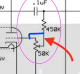
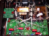
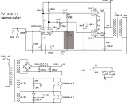
I drew a diagram from a photo! Not enough resistor 470 k Where did it go? he is not!
Where is he???? I circled the missing resistor on the diagram. Where is the second 470K resistor hidden???? if it is in this scheme?
Where is he???? I circled the missing resistor on the diagram. Where is the second 470K resistor hidden???? if it is in this scheme?
Attachments
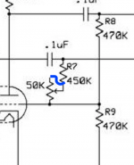
That 470k resistor has to be there somewhere. Under the board (2nd side)?
Otherwise there is no DC return through resistance to ground for both EL84 g1 grids. Will not work properly, if at all.
So, back to schematic # 1, the g1 grid resistors returning to ground are 470k for the top EL84; and 450k and the 50k Pot to ground for g1 of the bottom EL84.
Are you going to be able to get circuit boards, or are you going to point to point wiring?

kuly,
I do not know how you can order a board.
I hope someone else knows how you can get one.
Anybody?
Please tell kuly how he can order one of these PCBs.
Thanks!
Note: This thread started in 2006.
If the PCBs are no longer available then it will be necessary to:
Either build using point to point wiring, or selecting another amplifier circuit that has PCBs available.
Last edited:
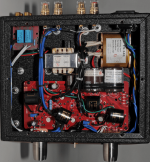
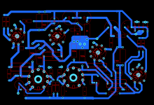
Hello ! Yes, I will make this one to order!
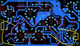
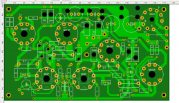
own board is blue - I hope there are no errors!
https://cart.jlcpcb.com/quote#/cart
this my amplifier plays well--but very complicated circuit
own board is blue - I hope there are no errors!
https://cart.jlcpcb.com/quote#/cart
this my amplifier plays well--but very complicated circuit
Attachments
Last edited:
- Home
- Amplifiers
- Tubes / Valves
- Yarland 34 ciii amp