I partially fixed hum on Miz Piggie using an RC post filter on the 400V B+ going to the output anodes. I used 2 X 270 ohm 3W resistors in parallel followed by a 220uF, 450V cap. This quieted things down to an acceptable level. I had tried an LC post filter, but I got some weird crackly noise at the amp outputs, and I didn't want to take the time to get to the root cause.
I took the pig with me to Burning Amp, and she did well with the higher efficiency speakers. People couldn't beleive such nice sounds were coming out of cheapo tubes and Hammond budget series output iron. I'll probably press her into service at home after putting some holes in the bottom plate for better interior ventilation.
Next up is Mister Piggy - I have some EL509s that would work a treat and no doubt blow off 40W dissipation without working up a sweat. I see no need to change the basic schematic, though I may use a better screen regulator for the 6JC6 input stage. Going to a higher output stage bias/output power ( I'm using 70 mA, ~400V now) means either turning up the plate voltage or ratcheting down the output transformer impedance to 3k. I'll have to ponder the implications of these alternate moves. Any comments form those who might have already been there?
I decided to keep the XFMR impedance at 5K and raise the output stage plate voltage. I've been buying up old Wurlitzer organ amps on Fleabay for salvage, and the power transformers are truly massive, probably as they are sized to power the rest of the organ as well. I dragged one to work to measure it up, and it has a nice 375-0-375V seconadry that should deliver over 500VDC even when loaded. It also has a 6.3-0-6.3V winding, a 5V winding, and a HV bias winding with a tap. If the size is any indication, it should have no problem powering what I have in mind. The output tubes in this case were 7868s. The output transformer measured to be 3.5K, which is kinda low, especially with such a high B+. It was also a bit on the small side. Strange design philosophy... I may use the output transformers in a small screen-driven sweep tube push-pull.
At any rate, I have a spare 16 X 8 X 2 chassis, which looks perfect for the underpinning for Mr. Piggy. Miz Piggy was a little too small, and the wiring is pretty crowded.
At any rate, I have a spare 16 X 8 X 2 chassis, which looks perfect for the underpinning for Mr. Piggy. Miz Piggy was a little too small, and the wiring is pretty crowded.
I was thinking (dangerous practice), and if the organ had a 16 ohm speaker, the reflected impedance at the transformder primary would be 7000 ohms, which makes a lot more sense considering the tubes and the plate voltages, and would allow a relatively wimpy output XFMR, which is what I've got. any comments from folks who've parted out Wurlitzers?
Onr caveat for those who might be thinking of building something like this. Take a look a the picture of Miz Piggy a few posts back - see that? Use a bigger chassis and place the iron a little farther away from the glass. The output tubes in the missus blow almost 30W apiece, and in extended listening tests (very satisfactory, if you must know), the tubes heat up both the output and power transformers. It's not a show-stopper - the power XFMR is probably at around 40C on the side facing the tubes, but it can be avoided with more generous spacing. It may be a problem with transformers that are painted black and run naturally hotter, so best to space things out and avoid some grief. Some holes in the chassis around the output tubes to provide ventilation would help, too.
For the sake of completeness, attached is a file showing the power supply schematic for Miz Piggy. It was dictated in part by the unique nature of the power transformer I happened to have lying around - a one-of-a-kind surplus buy. I used a second PC-mount transformer for the bias voltages. All the power supply stuff is on a piece of perf board that is attached to the transformer mounting bolts via spacers. If I had used a less cramped chassis space, things would have been laid out a bit differently. Folks wanting to duplicate this more or less with available iron would need a 540-560 VCT, 200 mA or greater transformer with a 6.3V filament winding with at least 6A capacity. Hammond has one. You would need to use a dropper resistor and a filter cap to power the source follower. A separate small transformer would still be needed for the bias voltages. A 24-0-24V transformer would work - these are readily available.
Unless there are other questions, that's it for this thread. When I have sufficient progress on "Mister Piggy" to warrent mention, I'll start a new thread.
Unless there are other questions, that's it for this thread. When I have sufficient progress on "Mister Piggy" to warrent mention, I'll start a new thread.
Attachments
This amp is being dragged out of its coffin for a few timely mods. The first touch is replacing the Neanderthal-ish RC B+ filter with a MOSFET capacitance multiplier to reduce some residual hummmmmm.
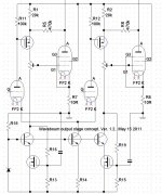
The next touch is to operate the output screen-driven stage in partial feedback mode, as the output screen-driven stage looks a whole lot like a modest pentode, anyway, with highish plate resistance.
The local feedback lowers the impedance of the output tube and makes it look more like a real triode than a sort of would-be pentode. Some residual gain will be left for global feedback to help straighten out the cheap output transformers.
More details when measurements settle down.
Last edited:
Also, the output tubes are changing from 6CD6G/GA to 6DQ5, a tube with higher plate dissipation rating and better ranked in Smoking Amp's "sweep tube list of fame". There's better ones on that list but I wanted to keep the octal socket and limit choice to tubes I already had on hand.
Those who want to see the effects of partial feedback vs. partial + global feedback can check out the "Sic Puppy" thread in the Pass forum. There I show before-and-after shots of square wave response with just partial feedback and partial with a touch of global feedback. The global feedback smartens up the square wave response quite a bit, without having all the feedback go through the transformer.
The thread in question is here:
http://www.diyaudio.com/forums/pass-labs/192450-sic-puppy-se-amp-using-semisouth-085-jfet-6.html
The post with the waveforms I mentioned is #55.
Last edited:
The 6EX6 is another cheap octal sweep tube, and was a compatible upgrade to the 6CD6GA.
6CB5A and 6CL5 also. Then there are the more expensive 26HU5 and 26LW6 which are octals too.
You will need more drive voltage swing from the front end with the local output plate feedback setup, assuming the Mosfet buffer will get a resistor after it to simulate current drive. The Schade scheme does work well at linearizing the tube, better than triode configured, but global N Fdbk will always give the best linear results if it can swallow the gain. (stay stable)
Wavebourn came up with a Schade variation a while back, where the (attenuated) output plate signal was fed back to a source degenerated P type Mosfet hanging from B+, which then acted as a varying plate current load for the input tube. That avoids the need for additional voltage swing from the input stage (no series R after follower), and also references the Schade feedback to B+ (instead of the usual ground), so avoiding (via current feed only to the input) the power supply noise issue in the feedback (which the typical Schade config. has).
Last edited:
Since the amp in question is only single-ended, drive is not as much of an issue as it would be for a push-pull, where the opportunities for abuse are much greater. I expect my input pentode (6JC6A) won't even break a sweat.
Of the other tubes you mentioned, I have only the 6CB5A, and the 6DQ5 fared better in the shootout ratings, if I remember correctly.
Anyway, the mods are in place, though I had to solder the top cap back on one of my 6DQ5s when the grippy National plate cap yanked it off - seems to be a problem with GE tubes. Some solder and JB-Quick did the trick for putting the cap back in place. Sometime this week I'll carefully power the amp up with a variac to see if all is still ok, and if so, to set the bias on the output stage.
This amp has never seen a Gain-Phase analyzer, just square wave testing. Its turn has come, as I definitely want to see what the cheapo Hammond 125ESEs do to the frequency response. I'll tack some Zobel networks to the output before testing, though, as it seems to be a must to get the gain to pass through zero and stay there.
Here is Wavebourn's idea and a link. It's a little different than I had remembered it yesterday.
But then I realized last night, that what I had mentioned, had the phasing wrong. One could also put the driver plate directly to the drain of the P-channel Mosfet (and bias the gate down from B+), but then it would need a buffer yet for driving a screen grid.
This type of approach has good PSRR, since only current sources cross between ground reference and B+. Unlike the usual shunt Fdbk resistor (usual Schade scheme).
http://www.diyaudio.com/forums/tubes-valves/205965-unusual-amps-64.html#post2919395
...............
Attachments
Last edited:
That's a lot of stuff - I'm trying the simple bonehead "Schade" approach first. The whole thrust of my effort here was to see what a couple of very simple mods would do for the amp. The partial feedback takes just one added resistor, and the capacitance multiplier for ripple reduction is an astounding five components, two of those being the protection zeners for the mosfet.
This was the very first tube amp I designed, though not the first I finished. That dubious honor goes to the "Shrine" amp, which is also undergoing mods.
This was the very first tube amp I designed, though not the first I finished. That dubious honor goes to the "Shrine" amp, which is also undergoing mods.
Last edited:
- Status
- This old topic is closed. If you want to reopen this topic, contact a moderator using the "Report Post" button.
- Home
- Amplifiers
- Tubes / Valves
- 6CD6GA in Enhanced Triode Mode for SE Amp