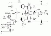
After having much trouble building a long tail pair splitter driving differential as a general use building block for PP amps. I ended up in a cascoded long tail pair around 6N6P double triode, using the included schematic.
The circuit with 10Vpp SE input (one side grounded) gives 150Vpp at each anode or a total of 300Vpp from anode to anode when loaded with 47K parallel with 220pf. Square is excellent to at least 30KHz as well as at 20Hz.
The problem is that when I load this with the output stage (2A3 PP). Even with no HT applied to the anodes of 2A3s (only filaments) the driver is clipping the upper side of the output waveform heavily but only when measured from anode to ground. When I measure this differentially (from anode to anode of 6N6) the distortion is obviously cancelled as is at the output of the amplifier. Noteworthy is the fact than when the driver is loaded with the ouput tubes the clipping is evident even at very low signals (i.e 5Vpp output). This gives me hell! can you propose whats happenning, or is this the way it supposed to be working(very unlikely)???
Any help would be appreciated
Attachments
panos29 said:with no HT applied to the anodes of 2A3s (only filaments) the driver is clipping the upper side of the output waveform heavily
Sounds like diode action here from G to K, coupled with leaky coupling caps?
I suggest that you DC couple your oscilloscope, set both channels to the same sensitivity, shift both traces to the centre line and put one probe on the grid and the other probe on the cathode of one 2A3. Increase the signal amplitude until the problem occurs and look at what the scope tells you.
What is the working current in your driver stage? From your description it sounds to me like you may have insufficient current drive to handle the small amount of grid circuit current present. (See third paragraph - if this is not the case you may have an inappropriately chosen operating point.)
Note that the positive waveform will clip when there is no plate voltage present because in a cathode (auto) bias amplifier there is no bias present either and you are essentially driving a shunt connected diode clipper to ground which is forward biased on positive going peaks.
When you apply plate voltage this should only happen once the positive peaks exceed the effective negative bias which should occur at something like +40Vpk at which point the output tube is effectively saturated unless you intended operation in A2 or AB2. If you can swing this type of voltage at the output of the driver before clipping you really don't have a problem, above this level the output tube grid will start to look like a diode and clip the waveform.
edit: add a couple of extra thoughts...
Kevin
So, I tried what suggested from EC8010 and the cathode remained a straight line moved to about -40V while grid got all the available swing. What I noticed though is that there is present a strange waveform at the output of the driver when no signal is present at the input. There is about 1Vpp trigonal wave like a hum or buz but at the top its becoming very complex like RF. When I ground the input the trigonal wave becomes clean and the "rf" is gone. I will try to reduce the grid leak of the input to 100K from 470k. So Kevin, you are sayng that when the drive signal to 2A3 becomes more than 40Vpp the signal will be rectified as the overdriven 2A3 grid will act as diode?
Increase your grid-stopper resistors from 100 Ohms to 1k and make sure they are right on the valve pins. In this very specific case, carbon resistors are better than metal film. Also try a 100n plastic capacitor from the top of the anode resistors to 0V and also one across the negative bias supply. The gate-stopper on the FET might be a bit small too, I often use 1k.
And yes, we are saying the 2A3 acts as a diode.
And yes, we are saying the 2A3 acts as a diode.
O.K
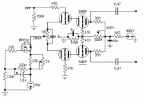
I finally got the time to listen to the completed amp, I also reduced the input grid leaks to 150K and indeed the "strange" waveform dissapeared. I also bypassed the balancing trimmer at the cathodes of the ltp with 1,5u and found that the gain slightly increased. I also changed the anode load from 15K to 30K with no noticeable change in performance, just some extra swing. What pazzles me though is that the operating point for the driver is kind of wierd to my knowledge. Soundwize, the amp is very nice with full bodied bass great extention and clarity and very good transient responce. There is some hum at 1inch from the cone but nothing to complain about, maybe I will add a mosfet at the driver power supply.
I finally got the time to listen to the completed amp, I also reduced the input grid leaks to 150K and indeed the "strange" waveform dissapeared. I also bypassed the balancing trimmer at the cathodes of the ltp with 1,5u and found that the gain slightly increased. I also changed the anode load from 15K to 30K with no noticeable change in performance, just some extra swing. What pazzles me though is that the operating point for the driver is kind of wierd to my knowledge. Soundwize, the amp is very nice with full bodied bass great extention and clarity and very good transient responce. There is some hum at 1inch from the cone but nothing to complain about, maybe I will add a mosfet at the driver power supply.
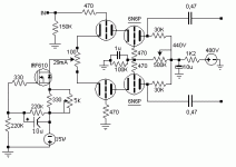
Bandersnatch said:One suggestion: attach the 100k Ec2 resistor to the CCS wiper instead of ground.
Good idea ,that way the cascode will be bootstrapped and the miller capacitance will diminish even more ...

Cheers
Excellent idea!
Wow! Douglas! thats a nice innovative idea! I like it alot and will try it this afternoon, after work.
On the other hand I gave it a shot with a friend's spectrum analyzer and overall at 10W output I got -75db 2nd and -70db 3rd. Not bad at all, also the amp is -1db at 7Hz and -1db at 51Khz. To my view these are signs of good sounding amp, especially considering the hammond 1650P tranformers used and junk part used throughout .
Also the driver is capable of 130Vpp per driver anode, or 260Vpp from anode to anode with extremely low distortion.
I really must say that the capacitor added across the 100ohm trimmer is now removed as it caused funny things to the output responce. I will post measurements of Vgk etc this afternoon.
Thanks for the help!
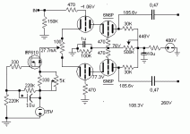
As promised earlier. Here is the schematic actually measured with the voltages shown as measured with a tektronix DM501 multimeter. The top tube Vak=108.3V, biased at Vgk=-2.6V. The lower tube got Vak=77.3V, at Vgk=-1.06V total current for all the long tail pair cascode 27.7mA. and voltage Vb=448V.
Attachments
Excellent, at last!
So having the prototype driver now fully built, I added the output stage consisting of a simple PP 2A3 biased at 265V 65mA, driving a hammond 1650P.
Last night I gave it a shot with a friend's spectrum analyzer and overall at 10W output I got -75db 2nd and -70db 3rd. Not bad at all, also the amp is -1db at 7Hz and -1db at 51Khz. To my view these are signs of good sounding amp, especially considering the hammond 1650P tranformers used and junk part used throughout . Maximum ouput at 8 ohm 15W with 5% distortion.
Also the driver is capable of 130Vpp per driver anode, or 260Vpp from anode to anode with extremely low distortion and the driver's gain is around 60. A problem remaining unsolved is that the maximum output is less than half of what my target was, but no complains here since it performs well.
- Status
- This old topic is closed. If you want to reopen this topic, contact a moderator using the "Report Post" button.
- Home
- Amplifiers
- Tubes / Valves
- Cascoded Long Tail Pair Inferno!


