So, finally after I built the whole amp, as in the schematic, I am listening with this for about a week now. The sound is good in general but suffers hugely on the dynamics department.
What I mean is that the sound is in general very flat, sounding like a very bad trasistorized amplifier. No sound stage "depth" no organs pinponting, no nothing. I am really pazzled here, how can an amplifier with such excellent measurements, sounding so bad? I tested this also with my small amp, a SE 2A3 driven direct coupled from a 5842. The differences are huge! The music is there! with excellent staging, excellent instrument pinpointing and focus.
Any ideas why this good measuring amplifier is sounding that "dead" and non involving?
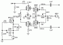
(Scematic attached is the actual one built)(measurements are @10W output -75db 2nd and -70db 3rd, bandwidth -1db @ 7Hz-51Khz.
What I mean is that the sound is in general very flat, sounding like a very bad trasistorized amplifier. No sound stage "depth" no organs pinponting, no nothing. I am really pazzled here, how can an amplifier with such excellent measurements, sounding so bad? I tested this also with my small amp, a SE 2A3 driven direct coupled from a 5842. The differences are huge! The music is there! with excellent staging, excellent instrument pinpointing and focus.
Any ideas why this good measuring amplifier is sounding that "dead" and non involving?
(Scematic attached is the actual one built)(measurements are @10W output -75db 2nd and -70db 3rd, bandwidth -1db @ 7Hz-51Khz.
Attachments
Dear Douglas, forgive my ignorance, can you explain me please why you are saying this will make a change? And if this indeed make a chage is there any chance with this modification the sound to become from nasty to excellent? I am asking as I really got no clue why after so much experimentation and fidling around and also after accomplishing such nice results (on measurements) the sound is so bad. Compared to the very mediocre measuring ZenV4 i got, the sound is even worse! I mean Zen is sounding awesome compared to the pushpull, although Zen measures very mediocre!
panos29 said:So, finally after I built the whole amp, as in the schematic, I am listening with this for about a week now. The sound is good in general but suffers hugely on the dynamics department.
What I mean is that the sound is in general very flat, sounding like a very bad trasistorized amplifier. No sound stage "depth" no organs pinponting, no nothing. I am really pazzled here, how can an amplifier with such excellent measurements, sounding so bad? I tested this also with my small amp, a SE 2A3 driven direct coupled from a 5842. The differences are huge! The music is there! with excellent staging, excellent instrument pinpointing and focus.
Any ideas why this good measuring amplifier is sounding that "dead" and non involving?
(Scematic attached is the actual one built)(measurements are @10W output -75db 2nd and -70db 3rd, bandwidth -1db @ 7Hz-51Khz.
Just because it measures good, does not necessarily mean that it will sound good. There are lots of SS amps out there with some awesome numbers and indifferent sound.
As for what's wrong here, it could be anything from incompatable speeks (especially in a no feedback amp, some will really "come alive" with the right speeks, and sound poor otherwise) to a slew rate problem due to inadequate drive (especially likely in a triode amp where Cmiller can become a problem) to unbalanced DC causing premature xfmr core saturation, or transients driving the cathode bias up and causing a less linear operation.
I prefer fixed bias, and the inclusion of a decent driver stage, and am generally not adverse to applying a bit of NFB either.
panos29 said:Dear Douglas, forgive my ignorance, can you explain me please why you are saying this will make a change? And if this indeed make a chage is there any chance with this modification the sound to become from nasty to excellent? I am asking as I really got no clue why after so much experimentation and fidling around and also after accomplishing such nice results (on measurements) the sound is so bad. Compared to the very mediocre measuring ZenV4 i got, the sound is even worse! I mean Zen is sounding awesome compared to the pushpull, although Zen measures very mediocre!
There is another amp builder out there who rigs his cascode front ends as you did. The reports I have gotten from friends who have heard them is parallel to your description of the amp you just built.
Either way, it's your amp...it is a simple mod, just re-wire a connection from ground to the wiper of the pot between your cathodes.
I'd hate to see you condemn PP amps based on a partially completed circuit. You can also help deal with the Miller C of your finals. It is just a matter of some small, precision caps...
")
cheers,
Douglas
Thanks everybody for answering, first of all there is no problem as far as the driver is concerned, in the sence that it can swing at least 50% more than needed by the output stage, neither is short of current as it is biased very high. The implementation is done on a kind of breadboard, meaning everything is bolted on 2 pieces of mdf, one is the power supply the other is the amp. all the front end is built on a piece of double sided pcb. Grounding arrangement is not a star one as this was just an experiment on driver topologies. My speakers are Tannoy monitir HPD dual concentric horn loaded at the back. I really tend to believe there is a problem with the audio "signature" of the particular driver arrangement-topology or something wrong with the power supply.
Panos,
the 'dioding' (what triggered this posting) is what I also encountered in a similar (6SN7 based) feed to a PP 10Y output. The most strange thing was that the kind of clipping (seen actually as inversing at the peak) also went back to my first stage (cascaded). When I added coupling capacitors between input first phasesplitter to second stage, decreased the Rgrid to ground on the output tubes and choose smaller caps there, the whole problem disappeared.
Dull sound. The HV regulator is based on FETS, I understand. Try creating an unregulated supply. I have made a HV shunt based on FET and 431 but indeed it lacked that special 'something'. A normal LRC is sweet. Dullness in details can sometimes have to do with a regulatorloop. Or else add some LRC stages after the regulator.
The negative long tail might be cut short in performance in the same way. There must be a possibility for you on the breadboard to get a long tail to a real negative voltage. Maybe you can try that (don't forget a strartup diode from cathode to earth).
Some strange trick: try a fixed resistor from the voltage divider to the grids of the top tubes, no cap after that, and stop resistors. The two grid currents must be in balance. A 47k resistor would be interesting. The resistor solve sthe problem of the CounterCurrent (the 'á rebours' from my signature in French is translated into Dutch as 'going counter current'). Just a thought...
Panos,
You're right in believing that you have encounterec a sonic signature. It is an easy thing to cure.
You also have a single MOSFET CCS. Using a double MOSFET cascode also makes a big difference. Big enough that after comleting the experiments, I will *NEVER* build a single transistor current regulator again.
NEVER.
You are sooooo close.
cheers,
Douglas
Funny thing is that when I was experimenting with a similar project using an long tail pair with 6H6Pi with exactly the same costant current source and 6080s as output tubes (same OPTs) the sound was excellent. The sonic signature was very similar to my 2A3 SE amp which I really like.
The power supply was the same, but the driver had the same PS as the output stage 330V (tube rectified CLC, no regulator). The only thing was that the driver could not swing much AC, so the output was only around 5-6 W. This project got me started experimenting with different driver topologies (i tried all differential - LTP topologies, targeting for increased bandwidth, swing and minimal distortion with no feedback), like the current differential cascoded. The only simple stage which accomplished these targets was the cascoded LTP.
The power supply was the same, but the driver had the same PS as the output stage 330V (tube rectified CLC, no regulator). The only thing was that the driver could not swing much AC, so the output was only around 5-6 W. This project got me started experimenting with different driver topologies (i tried all differential - LTP topologies, targeting for increased bandwidth, swing and minimal distortion with no feedback), like the current differential cascoded. The only simple stage which accomplished these targets was the cascoded LTP.
full schematic with measurements
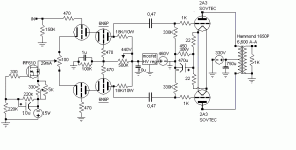
Here is the actual power supply used, including the actual measurements taken on the circuit. I got to note that the transformer providing 2X350V for the output stage, is getting very hot (touchable) after the first hour, as the unit is marginal for the current consumption. Anyway I had an idea, what would happen if I attached another current source at the common point of the output tubes (where the 22ohm resistors join)?
Here is the actual power supply used, including the actual measurements taken on the circuit. I got to note that the transformer providing 2X350V for the output stage, is getting very hot (touchable) after the first hour, as the unit is marginal for the current consumption. Anyway I had an idea, what would happen if I attached another current source at the common point of the output tubes (where the 22ohm resistors join)?
Attachments
- Status
- This old topic is closed. If you want to reopen this topic, contact a moderator using the "Report Post" button.
- Home
- Amplifiers
- Tubes / Valves
- Cascoded Long Tail Pair Inferno!