The sound with feedback from the U/L taps was a very detailed but a bit "coloured". The frequency response seemed to be too dependent on the speakers impedance vs frequency curve. It was better (less dependent on speaker Impedance vs frequency) with feedback from the anodes. This based entirely on listening using VAF Research DCX10 Generation 2 speakers.
For the 6V6 I also used 10K Raa Output trannies because that suits 6V6 in U/L a bit better and was what I had but 8K is fine.
The earlier version I did for niece Jessica was also 6SL7 and 6V6 but with tube rectifier and Polypropylene main filter caps. I liked that so much I wanted to do another but with SS rectifier and "ordinary" electrolytic caps. My final conclusion was that the tube rectifier didn't improve things but the polypropylene caps did. The main polypropylene caps were 60uF/900V "Pulse Grade" caps from a New Zealand manufacturer which someone had rebranded as "Audiocentric".
Cheers,
Ian
Thank you for this very interesting information, including the beneficial audible effect of the polyropelene PS caps. Perhaps more personal experimentation is in order with the FB scheme. I will try both anode and screen FB with my DIY Elsinore (Joe Rasmussen’s) speakers with benign impedance curves and report back here.
You should enter 100 x 80 mm max !
I modified the Pcb to be just under 100 mm and put round corner "à la Prasi"
It should be at 5 $ for 10 pieces now...
Marc
I have a spare pair of the ECL86 boards. If somebody is interested please let me know $24 to anywhere should cover it.
Would these transformers work for the Baby Huey EL84 pcb boards from the group buy in the DIY fourm
EDCOR - DAP-202


EDCOR - DAP-202
The output transformers will work fine, but I have doubts about the power transformer’s ability to heat the tubeset, provide sufficient voltage and lacks a supply for the bias supply.
1. The EL84 Baby Huey heaters require 4x760 ma (EL84), plus 2x300 ma for a total of 3.64 amp at 6.3v. The Edcor spec says 3 A @ 6.3v. However, that is exactly what the OddWatt amp requires and the transformer was specified for it.
2. The EL84 BH will probably work with a 180 VAC transformer, but the better transformer is one that provides around 230 VAC.
3. If you can’t find a power transformer that includes around 50 vac for the bias supply, you could add a separate small transformer.
I suggest your read post #226 and what follows beyond that on the topic of Power transformers. Marc suggested an inexpensive solution using separate transformers. My personal choice for a single transformer will probably be this Edcor power transformer, but observe Marc’s caution about using it. EDCOR - XPWR078
Hope this helps.
Last edited:
In my post above the the post numbers refer to this thread:
EL34 Baby Huey Amplifier
EL34 Baby Huey Amplifier
Thank you. I will see if they have them with those power specs.
Thank you for the information
Alright, I've bought the parts for the preamp that will (eventually) drive my baby hueys, and ordered the transformers from edcor. I got a pair of xpwr064s, and called edcor about adding 6 ohm taps to the cxpp24-8k, which they graciously added at no extra charge
However, I'm now faced with a dilemma. My speakers are RATED at 99db/W(not sure how accurate this is, as they're a fairly new DIY design). I have an old receiver I've been using to drive them until now which is rated at 50W, so I keep the volume as low as it can go. My question is:
The EL34 seems to put out about 50W, but seems to have more of the tone I am looking for (warmer mids, better bass). My transformers are only rated for 25W, and my speakers would never use all this power. Is there a way to limit the power put out by these tubes without having to redesign much of the circuit? Are there significant tonal differences between the EL34 and the EL84, or are they just different power ratings?
I guess at the end of the day, I'm leaning hard towards the EL84, but have been hesitant to pull the trigger.
Hello Adam
I would like to ask you if you finally built the amplifier Baby Huey with tubes EL 84 according to the schematics you have uploaded to your page. If YES what are your impressions
Thank you very much
I've been sourcing power transformers for mono versions of this amp.
Here's what I've found to be adequate. Please tell me if there are any known disadvantages to using smaller transformers instead of one large one.
Plate and heaters:
Hammond 261G6 250V CT @ 130ma, 6.3V @ 2A
CCS 5V:
Hammond 167M5 5V CT @ 3A (higher current ratings available) ...and I honestly don't know what to do with the centre tap.
With this setup you would need one of each of these for one channel/ board?
So for both boards you would need 2 of each
And then the output transformers with 4/8 ohm taps
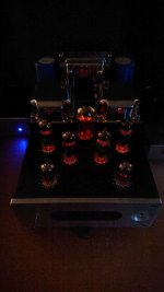
It's alive!
Hi all,
fired my BH up some days ago. No smoke, wonder that. Some building details and pictures here. Gingertube somewhere wrote "never chose a small case". Da**ed, haven't read it in time . Now I can really feel with him regarding the pain ...
I wanted to realize a tube rectification with 5AR4, as I already had a PT with 2x 250V / 2x 350V. Result: first voltage too low, second too high, even after the 10H choke. Trials with resistors etc. in the B+, giving a RCLC, leaded all in all to the following experience: Sounds like crap.
So I switched back to the lower rails, resulting in roughly 300V B+, 260V plate. I switched R16 (is it 16? Don't have the schematics here at present) at the bottom of the CCS from 560R to a trimmer to get the anode voltage of the ECC83 up to 160 V. 140 V sounded a little bit "tired". Value of the resistor would now roughly be 1,3k. That will be changed back to a fixed resistor afterwards. Current is equal on both sides.
What takes me wonder is the Bias for the EL84: 38mA? Sounds quite high to me? I'm definetely not an expert, but even all calculators or webpages from other guys are talking about 21-30 mA, depending on the B+?! Before having a set of fried tubes lying on the bench, I went somewhat lower.
Measurements done (rounded):
Signals are now looking almost perfect, see Sinus left/right in comparison and as an overlay. Even more important: sounds really good with values like above! Haven't had so much time to listen yet, but even now I'm really impressed.
Any comments / suggestions on this?
Thanks for sharing your ideas and time! For not getting bored out, a set of PCB for the EL34 BH are on their way.
Hi all,
fired my BH up some days ago. No smoke, wonder that
. Some building details and pictures here. Gingertube somewhere wrote "never chose a small case". Da**ed, haven't read it in time . Now I can really feel with him regarding the pain ...I wanted to realize a tube rectification with 5AR4, as I already had a PT with 2x 250V / 2x 350V. Result: first voltage too low, second too high, even after the 10H choke. Trials with resistors etc. in the B+, giving a RCLC, leaded all in all to the following experience: Sounds like crap.
So I switched back to the lower rails, resulting in roughly 300V B+, 260V plate. I switched R16 (is it 16? Don't have the schematics here at present) at the bottom of the CCS from 560R to a trimmer to get the anode voltage of the ECC83 up to 160 V. 140 V sounded a little bit "tired". Value of the resistor would now roughly be 1,3k. That will be changed back to a fixed resistor afterwards. Current is equal on both sides.
What takes me wonder is the Bias for the EL84: 38mA? Sounds quite high to me? I'm definetely not an expert, but even all calculators or webpages from other guys are talking about 21-30 mA, depending on the B+?! Before having a set of fried tubes lying on the bench, I went somewhat lower.
Measurements done (rounded):
- B+ (biased at ~26 mA/tube): 290 V
- After choke: 275 V
- Plate: 270 V
- Bias: 26 mA/EL84
- Anode ECC83: 160V
- Grid EL84: -10,5 V
- Grid ECC83: -1,7V
- Measured Power at 8 Ohms (begin of clipping, 1kHz sin.): 7 W
- Measured Power at 4 Ohms (dto.): 6 W
Signals are now looking almost perfect, see Sinus left/right in comparison and as an overlay. Even more important: sounds really good with values like above! Haven't had so much time to listen yet, but even now I'm really impressed.
Any comments / suggestions on this?
Thanks for sharing your ideas and time! For not getting bored out, a set of PCB for the EL34 BH are on their way
.Attachments
Great looking job
Do you have a parts list for the power transformer and output transformers and other items you put into it that where not in the board? Not counting the rca and items on the back. I have these boards and still need to build them and only have the parts kit from the group buy from Mouser
Do you have a parts list for the power transformer and output transformers and other items you put into it that where not in the board? Not counting the rca and items on the back. I have these boards and still need to build them and only have the parts kit from the group buy from Mouser
Last edited:
Officially, EL84 in a push-pull configuration can take up to 300V on their plates and 40mA per tube (making 80mA for the pair) in bias current.
These are the datasheet values which are safe for the tubes.
Most Hifi & guitar amp makers in the heyday of tubes ran the EL84 in excess of that. They can take some abuse on some parameters if you respect the total power envelope in the long term.
For me, your bias around 20mA is a bit low. I would go to 40mA per tube, as your anode voltage is lower than 300V.
Yves
Thanks a lot for your comments, highly appreciated!
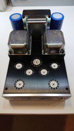
For sure. Here's a short list:
The rest is more or less what is described in this thread, despite the resistors. Whereever possible I use Carbonite resistors. I like them more than MOX or metal film. Only in areas with higher wattage metal-R are used.
Due to the lack of space I had to build in a "second floor". Maybe you can see the base, where the toroid is mounted on? That's a FR4 board, copper on the bottom and connected to earth. Underneath are the connectors for the OPT, the fuses for the 5AR4 (one 250 mA fuse on each primary, followed by a UF4007 to prevent backfire from the carburetor)
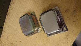
What else? The covers on the trannies as well as the parts like mentioned above have been bought at Frag Jan zuerst --- Ask Jan First. The toolmaker inside could not let the covers look like delivered, so they got polished.
For the PT I had to tweak a little bit to get the cover on the connection side without building an automatic fuse-blower. For that I designed a kind of spacer and printed it on my 3D-Printer. Electrical connection of the isolated part to earth then was done by an extra wire on the bottom.
As I have several things I like to do after work, I prefer to repair or rework the stuff sold on the net (slight traces of usage) as well as DIY. For sure there's more to Baby Huey with f.e. expensive Iron, but for now I'm really satisfied!
Abbendum: A lot of 4 Reflektor 6P19P-EV is on the fly to me / to my BH. Looking forward to it!
Best regards from the basement!
Ingo
Do you have a parts list for the power transformer and output transformers and other items you put into it that where not in the board? Not counting the rca and items on the back. I have these boards and still need to build them and only have the parts kit from the group buy from Mouser
For sure. Here's a short list:
- PT "Ausgangstrafo 340" from TBT (link below) 54,-€
Pri: 230 Volt 50/60 Hz 130 VA
Sec: 1 x 350-250 -0- 250-350 Volt / 2x 120 mA
Designed for tube rectification.
1 x 0 - 6,3 Volt / 5 A
1 x 0 - 5,0 Volt / 3A
1 x Shield
Size: M102-36 (102 x 102 x 36 mm)
Sec: 1 x 350-250 -0- 250-350 Volt / 2x 120 mA
Designed for tube rectification.
1 x 0 - 6,3 Volt / 5 A
1 x 0 - 5,0 Volt / 3A
1 x Shield
Size: M102-36 (102 x 102 x 36 mm)
- OPT ATR 30
Max. 18 Watt
Pri: 8000 Raa
Sec.: 4 und 8 Ohm
8x interleaved
Size: EI96-35 (96 x 80 x 35 mm)
Pri: 8000 Raa
Sec.: 4 und 8 Ohm
8x interleaved
Size: EI96-35 (96 x 80 x 35 mm)
- Torodial PT
1x Audio Grade 50VA PRI:230V SEC
2x 6,4V (0,5A)
1x 5,1V (0,5A)
1x 50 V (0,5A)
2x 6,4V (0,5A)
1x 5,1V (0,5A)
1x 50 V (0,5A)
- Soft-Start for Torodial
(right upper corner) - 6A Diode, 48V Relais, a few resistors - nothing uncommon.
The rest is more or less what is described in this thread, despite the resistors. Whereever possible I use Carbonite resistors. I like them more than MOX or metal film. Only in areas with higher wattage metal-R are used.
Due to the lack of space I had to build in a "second floor". Maybe you can see the base, where the toroid is mounted on? That's a FR4 board, copper on the bottom and connected to earth. Underneath are the connectors for the OPT, the fuses for the 5AR4 (one 250 mA fuse on each primary, followed by a UF4007 to prevent backfire from the carburetor
)What else? The covers on the trannies as well as the parts like mentioned above have been bought at Frag Jan zuerst --- Ask Jan First. The toolmaker inside could not let the covers look like delivered, so they got polished.
For the PT I had to tweak a little bit to get the cover on the connection side without building an automatic fuse-blower. For that I designed a kind of spacer and printed it on my 3D-Printer. Electrical connection of the isolated part to earth then was done by an extra wire on the bottom.
As I have several things I like to do after work, I prefer to repair or rework the stuff sold on the net (slight traces of usage
) as well as DIY. For sure there's more to Baby Huey with f.e. expensive Iron, but for now I'm really satisfied!Abbendum: A lot of 4 Reflektor 6P19P-EV is on the fly to me / to my BH. Looking forward to it!
Best regards from the basement!
Ingo
Attachments
Last edited:
Hi all,
fired my BH up some days ago. No smoke, wonder that
I wanted to realize a tube rectification with 5AR4, as I already had a PT with 2x 250V / 2x 350V. Result: first voltage too low, second too high, even after the 10H choke. Trials with resistors etc. in the B+, giving a RCLC, leaded all in all to the following experience: Sounds like crap.
So I switched back to the lower rails, resulting in roughly 300V B+, 260V plate. I switched R16 (is it 16? Don't have the schematics here at present) at the bottom of the CCS from 560R to a trimmer to get the anode voltage of the ECC83 up to 160 V. 140 V sounded a little bit "tired". Value of the resistor would now roughly be 1,3k. That will be changed back to a fixed resistor afterwards. Current is equal on both sides.
What takes me wonder is the Bias for the EL84: 38mA? Sounds quite high to me? I'm definetely not an expert, but even all calculators or webpages from other guys are talking about 21-30 mA, depending on the B+?! Before having a set of fried tubes lying on the bench, I went somewhat lower.
Measurements done (rounded):
- B+ (biased at ~26 mA/tube): 290 V
- After choke: 275 V
- Plate: 270 V
- Bias: 26 mA/EL84
- Anode ECC83: 160V
- Grid EL84: -10,5 V
- Grid ECC83: -1,7V
- Measured Power at 8 Ohms (begin of clipping, 1kHz sin.): 7 W
- Measured Power at 4 Ohms (dto.): 6 W
Signals are now looking almost perfect, see Sinus left/right in comparison and as an overlay. Even more important: sounds really good with values like above! Haven't had so much time to listen yet, but even now I'm really impressed.
Any comments / suggestions on this?
Thanks for sharing your ideas and time! For not getting bored out, a set of PCB for the EL34 BH are on their way
Beautifully done.
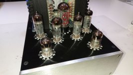
BH with 6V6 outputs
Where to get good output transformers for BH for a 6V6 PP output? Especially 10k PP UL types?
Gingertube wrote that for personal listening he prefers his 6V6/6SL7 implementation of Baby Huey with 10k ohm output transformers. This suggested that output transformers with 10k primaries were better for 6v6 BH implementations than the more-easily found 8k output transformers.
I thought I would share with prospective BH 6V6 implementers an OT source of this sort that I discovered. Toroidy from Poland has an offering (toroidal of course) that seems to be ideal for BH 6V6 amplifiers. UL 10k primaries and 4 and 8 ohm outputs, and at 25VA capability sufficient for 6V6 amplifiers. The TTG-ECL86PP is available at a great price from TME (I recently paid US$46 each). (I have no commercial relation, other than being a happy customer.
See: TTG-ECL86PP TOROIDY - Transformer: speaker | 25VA; O90x55mm; 0.01/43kHz; 150mA | TME - Electronic components
Hi,
based on new page on Merlin's site:
The Valve Wizard
It is easy to develop a system to autobias this amp at every startup (or on demand). Who's interested into implementing it on the project?
I will post this comment on both EL84 and EL34 threads.
based on new page on Merlin's site:
The Valve Wizard
It is easy to develop a system to autobias this amp at every startup (or on demand). Who's interested into implementing it on the project?
I will post this comment on both EL84 and EL34 threads.
....based on new page on Merlin's site:
The Valve Wizard
It is easy to develop a system to autobias this amp at every startup (or on demand). Who's interested into implementing it on the project?
I will post this comment on both EL84 and EL34 threads.
Great suggestion! I would be very interested! Please lead the way!
Ian,
I recently spent many, very pleasant hours reading the BH saga in preparation for my first build using the GB3 boards.
Unless I missed a later update you are listening to a 6sl7/6v6 BH most regularly at this time. If you don’t mind, I have a few questions regarding it.
1. Did you build it according to the schematic in your post #604, including the shunt feedback taken from the UL taps. If not, which schematic did you follow?
2. If yes, were any modifications to #604 needed to accomodate the 6SL7.
3. What power supply changes were made to the PS in your post #602.
4. Could you please comment on why you are using this version, rather than the EL84 BH, which you thought was more accurate, etc.
Thanks so much.
Francois
Francois,
Did you end up building the amp with the 6SL7?
Thanks,
Greg
- Home
- Amplifiers
- Tubes / Valves
- EL84 Amp - Baby Huey