Description
The 6P15P (6П15П) output pentode is designed for amplification of output video-frequency voltage in television equipment.
The 6P15P output pentodes are miniature devices enclosed in glass bulb and are provided with a nine-pin base and an indirectly heated oxide-coated cathode.
The 6P15P electorn tube output pentodes are resistant to ambient temperature from -60 to +70°C and relative humidity of 95 to 98% at +40°C, as well as to mechanical loads: vibration loads up to 2.5g and multiple impact loads up to 35g.
All tubes new, military equipment and have "OTK" mark. Near equivalent: EL83, SV83 and 6P1T. The tube is manufactured by the Reflector plant, Saratov, Russia.
General characteristics:
Name: 6P15P
Type: output pentode, hi-durable
Application: amplification in special equipment
Cathode type: oxide, indirect heating
Envelope: glass, miniature
Mass, g: 20
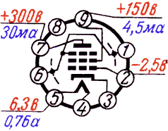
Filament voltage, V: 6,3
Filament current, A: 0,7-0,82
Anode voltage, V: 300
Anode current, mkA: 1
Anode power, W: 12
Grid2 voltage, V: 150
Steepness, mA/V: 12,0-17,4
Reverse grid current, uA: 0,7
Microphnic noise, mV: 250
Gain: 25
Socket type: rsh8
All datasheets here.
The 6P15P (6П15П) output pentode is designed for amplification of output video-frequency voltage in television equipment.
The 6P15P output pentodes are miniature devices enclosed in glass bulb and are provided with a nine-pin base and an indirectly heated oxide-coated cathode.
The 6P15P electorn tube output pentodes are resistant to ambient temperature from -60 to +70°C and relative humidity of 95 to 98% at +40°C, as well as to mechanical loads: vibration loads up to 2.5g and multiple impact loads up to 35g.
All tubes new, military equipment and have "OTK" mark. Near equivalent: EL83, SV83 and 6P1T. The tube is manufactured by the Reflector plant, Saratov, Russia.
General characteristics:
Name: 6P15P
Type: output pentode, hi-durable
Application: amplification in special equipment
Cathode type: oxide, indirect heating
Envelope: glass, miniature
Mass, g: 20
Filament voltage, V: 6,3
Filament current, A: 0,7-0,82
Anode voltage, V: 300
Anode current, mkA: 1
Anode power, W: 12
Grid2 voltage, V: 150
Steepness, mA/V: 12,0-17,4
Reverse grid current, uA: 0,7
Microphnic noise, mV: 250
Gain: 25
Socket type: rsh8
All datasheets here.
ilorev:
Do you have actual experience with 6P15P tubes and have you experienced screen grid failure at voltages above 150V? If so I would like to know more about the circumstances. I think 150V is overly conservative.
I know of at least one “genuine Russian tube data book”* that shows 6P15P maximum Ug2 = 330V, same as anode max. This could be an error, of course, but the book even has a set of performance curves with Ug2 at 200V.
IIRC George of Tubelabs, who likes to torture tubes until they fail, concluded that 6P15P does not survive with screen voltage over 200V. Yet, I have seen plenty of anecdotes, especially in the guitar world, that people made the necessary jumper in the EL84 socket and plugged in 6P15Ps with good results (and little evidence of failures). So, it would be nice to collectively get some facts of actual maximums for 6P15P Ug2 and determine some fact-based recommendations. As stated earlier, I’m planning to build a 6P15P Baby Huey, and could use such recommendations.
* See: electron Tube Data sheets - Mashpriborintorg documents
Last edited:
6P14P-6P15P-Always remember that g2-pin 9 maximum 150 volts
Jumper pins 1-3 or 3-6.
6P15P very nice sound
Max 150 volts g2 ... referred to 6P15P .. clearly
Thanks Ilorev for the clarifications
I have verified the BHEL84 PCBs and it looks correct for 6P14,
") correct me if I'm wrong
correct me if I'm wrongIn guitar amps (VOX AC-15 for example), I am amazed at how many people are being repaired with 6P15, maybe in the pentode setup they go down + B with higher Rg2, but others consider them direct replacement.
IIRC George of Tubelabs, who likes to torture tubes until they fail, concluded that 6P15P does not survive with screen voltage over 200V. Yet, I have seen plenty of anecdotes, especially in the guitar world, that people made the necessary jumper in the EL84 socket and plugged in 6P15Ps with good results (and little evidence of failures). So, it would be nice to collectively get some facts of actual maximums for 6P15P Ug2 and determine some fact-based recommendations. As stated earlier, I’m planning to build a 6P15P Baby Huey, and could use such recommendations.
Alas, my memory proved to be wrong; what George tested were 6CW5s, with max 200V screens. The rest is still good.
If 6P15P = EL83, then...?
I believe the Russian 6P15P is pretty much the same thing as an EL83.
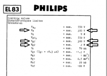
If that's correct, then the max Va and Vg2 voltages should be 300V, as seen on the Philips EL83 data sheet.
Or, it might be more like the PL83 (except with a 6.3V heater), which states the max Va and Vg2 are both 250V.
No?
I believe the Russian 6P15P is pretty much the same thing as an EL83.
If that's correct, then the max Va and Vg2 voltages should be 300V, as seen on the Philips EL83 data sheet.
Or, it might be more like the PL83 (except with a 6.3V heater), which states the max Va and Vg2 are both 250V.
No?
Attachments
My reference in the case of Russian valves has always been:
Tube Tester Files - 6П15П - 6Pi15Pi (SV83)
Tube Tester Files - 6П15П - 6Pi15Pi (SV83)
My reference in the case of Russian valves has always been:
Tube Tester Files - 6П15П - 6Pi15Pi (SV83)
I don't have any 6P18P, as they are more difficult to find.
Klausmobile is how I (and a lot of us) first heard of these Russian tube types.
The Klausmobile measurements are great, but they're all done at low voltages, so they don't tell us what the max screen voltage would be for the tube types in question.
--
Operating conditions for the BH 12ax7
I’m trying to understand the operating conditions of the 12ax7 for the BHEL84. This started with Bas Horneman’s thread on the topic of the CCS that sets some of the conditions, and specifically the CCS current.
Could you check the values for this current source?
Based on that and his review of this long thread he concluded the CCS should run 1 ma, i.e. 0.5 ma for each triode. That in his builders thread here:
https://www.diyaudio.com/forums/tubes-valves/351919-oh-baby-huey-el84-build-6.html#post6167748
Since this is a design rather than builders issue I would like to bring the topic up here.
I looked at the 12ax7 loadlines at 0.5 ma fixed by the CCS. I expect ~130v on the plates (310/440*189) based on gabo‘s post in the BHEL34 thread. He measured 189v on the 12ax7 plates for his EL34 build with 440v B+, and with his R18 at 680k. That means 1.6 ma; 0.8 per triode. That seems to be a better operating region in the loadlines, than the one for BHEL84 under the conditions mentioned.
Since gingertube designed the BHEL84 to run 0.5 ma on the 12ax7 triodes (based on Bas’s review of the thread) something could be wrong in my analysis. Something probably is, since a lot of BHEL84 had made a lot of people happy. I hope someone more knowledgeable could help to explain the apparent discrepancy wrt. the best operating regions of the loadlines.
It would be very helpful if someone with a completed BHEL84 could measure your plate voltage (since 130v is a guesstimate of it), cathode voltage and voltage across R18 (assuming 1k, or mention what was used). Please also state your B+ at the OT centertap.
Attachments

Let me try to dig into the working condition of the ECC83.
Presume Va (of the EL84) = 315V and Ia = 35mA (somewhat less then CCS , minus screen current !).Gives -Vg1=12V and ΔVa=215V (UL down to 100V) resulting in a gain of 215/12=~17x (will be used later on).
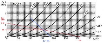
Now DC conition of the triode.Since the voltage on both sides of the 16k are the same we can forget that for now.So Ra = 220+47=267k and Vb=315V, and we can draw a load line.With the Ia=0,6mA we get a working point at Va=155V.
On with the dynamic load line.
The center of the 16k doesn't move, if one side goes up the other side goes down the same amount, and we get a voltage divider from the EL84 anode 47k to 8k = division 1/7.On the end of the 220k there is 47k//8k and a voltage 17x/7 = ~2,5 x signal on g1(EL84)=a(ECC83).
The anode ECC83 sees (220k+47k//8k)/(2,5+1)=64k and the 470k (grid leak EL84) in parallel.Makes a total dynamic load of 56k.
Looking at the curves the current could go up to 0,7mA but not more to stay out of the grid current region.
Mona
Presume Va (of the EL84) = 315V and Ia = 35mA (somewhat less then CCS , minus screen current !).Gives -Vg1=12V and ΔVa=215V (UL down to 100V) resulting in a gain of 215/12=~17x (will be used later on).
Now DC conition of the triode.Since the voltage on both sides of the 16k are the same we can forget that for now.So Ra = 220+47=267k and Vb=315V, and we can draw a load line.With the Ia=0,6mA we get a working point at Va=155V.
On with the dynamic load line.
The center of the 16k doesn't move, if one side goes up the other side goes down the same amount, and we get a voltage divider from the EL84 anode 47k to 8k = division 1/7.On the end of the 220k there is 47k//8k and a voltage 17x/7 = ~2,5 x signal on g1(EL84)=a(ECC83).
The anode ECC83 sees (220k+47k//8k)/(2,5+1)=64k and the 470k (grid leak EL84) in parallel.Makes a total dynamic load of 56k.
Looking at the curves the current could go up to 0,7mA but not more to stay out of the grid current region.
Mona
Attachments
Let me try to dig into the working condition of the ECC83.
Presume Va (of the EL84) = 315V and Ia = 35mA (somewhat less then CCS , minus screen current !).Gives -Vg1=12V and ΔVa=215V (UL down to 100V) resulting in a gain of 215/12=~17x (will be used later on).
Mona
Mona, thanks very much for this analysis and patient explanation. It helps me, and I’m sure others, towards understanding this design. But I have several more follow-up questions/clarifications. (I you don’t want to bother I will sure understand). I will start at the beginning with the quote above, working through other parts later towards your conclusion. The plan is to compile this evolving analysis and add it to the Baby Huey Wiki for future edification of builders.
1. I follow up to “somewhat less then CCS , minus screen current”. CCS=? Constant current source? It appears you mean cathode current.
2. Please explain “UL down to 100V).
3. For the record, which schematic are you using to develop your explanation? (It appears that you are using gingertube’s original schematic without the “power-driver Mosfets” since you referred to a grid leak resistor of 470k, which appears in the original, but not latest design which is of the most interest).
I wonder if this discussion should be moved to the original Baby Huey EL84 thread, where others might find it useful, and not foul Bas’s nice building-oriented thread.
More later, if you please.
Thanks,
Francois
Last edited:
No problem, time to waste in a resthomeBut I have several more follow-up questions/clarifications. (I you don’t want to bother I will sure understand).
Constant current is the cathode current.I want the anode current to find out from the curves (pentode) what the resulting -Vg1 is.So I take a couple of mA off for the screen current.Nowing bias -Vg1 gives the max swing the input to the output tubes makes to get to max Ia at Vg1=0.1. I follow up to “somewhat less then CCS , minus screen current”. CCS=? Constant current source? It appears you mean cathode current.
As Vg1 goes up to zero the anode current goes up too and the anode voltage drops.At Vg1=0 the voltage on the anode is minimal, pulling the load down, how much depends on the load.2. Please explain “UL down to 100V).
As a pentode the tube can go as low as <50V and still pulling much current.But with UL the screen voltage goes down with the anode and the anode needs more voltage to pass so much current.
With Raa=8k it goes not down more then ~110V and with Raa=10k (less current) to ~90V.
I asumed 100V.Comming from 315V give an output (anode) swing of 215V as a result of 12V on the input (grid).
It's the schematic from 07-2011.The mosfet in between doesn't change much, the gain being ~1x.3. For the record, which schematic are you using to develop your explanation?
By the way, the loadline is more complicated then what I have showed.The gain of the final stage isn't constant and consequently the effective resistance of the 220k is not constant resulting in a curved loadline.
Mona
No problem, time to waste....
It's the schematic from 07-2011.The mosfet in between doesn't change much, the gain being ~1x.
By the way, the loadline is more complicated then what I have showed.The gain of the final stage isn't constant and consequently the effective resistance of the 220k is not constant resulting in a curved loadline.
Mona
Mona,
Thanks very much for your reply. Hopefully it is not time wasted
After this, at the very least, there will be a smarter me! I’m good with 1 & 2. Re. 3. Could we continue with 3.?
3. (continued) The BHEL84 later design (Nov 19, 2018, for the recent PCB) with mosfet driver doesn’t have a grid leak resistor per se, but it does have a 1M resistor to the gate of the Mosfet. Does the EL84 “see it beyond the Mosfet” as if it is a grid leak resistor? The datasheets say max grid leak for a fixed bias EL84 is 0.3M, is this then a problem?
Now DC condition of the triode. Since the voltage on both sides of the 16k are the same we can forget that for now.So Ra = 220+47=267k and Vb=315V, and we can draw a load line.With the Ia=0,6mA we get a working point at Va=155V.
4. Why do you choose Ia=0,6mA? Is this a guesstimate of where we might end up at? I’m not sure why you draw this load line. Is this a static loadline, followed by the dynamic load line next?
On with the dynamic load line.
The center of the 16k doesn't move, if one side goes up the other side goes down the same amount, and we get a voltage divider from the EL84 anode 47k to 8k = division 1/7. On the end of the 220k there is 47k//8k and a voltage 17x/7 = ~2,5 x signal on g1(EL84)=a(ECC83).
The anode ECC83 sees (220k+47k//8k)/(2,5+1)=64k and the 470k (grid leak EL84) in parallel. Makes a total dynamic load of 56k.
5. I’m a little lost here with “ ~2,5 x signal on g1(EL84)=a(ECC83).” This is the feedback applied to the ECC83 anode from the output transformer, right?
6. Could you explain the equation “anode ECC83 sees (220k+47k//8k)/(2,5+1)=64k”. I understand the parts of the equation and where you got them, except I don’t understand “+1” , but what are you calculating and how? Were did the grid leak resistance appear here?
Looking at the curves the current could go up to 0,7mA but not more to stay out of the grid current region.
7. Do you consider this operating condition a good one? If not what could be done to improve?
With the original setup there is a 470k on the anode of the ECC83, the coupling-C is a short circuit for the signal.3. (continued) The BHEL84 later design (Nov 19, 2018, for the recent PCB) with mosfet driver doesn’t have a grid leak resistor per se, but it does have a 1M resistor to the gate of the Mosfet. Does the EL84 “see it beyond the Mosfet” as if it is a grid leak resistor? The datasheets say max grid leak for a fixed bias EL84 is 0.3M, is this then a problem?
So it's in parallel with the anode resistor for the dynamic behavior (signal).
The mosfet has 1M as gate leak and replaces the 470k, makes not much difference parallel with 64k.
The grid of the EL84 is connected to the source of the mosfet, much better then 0,3M, it can't run away.
Bas had 0,6mA in his amp, so I used that to determine the operating point on the static loadline.4. Why do you choose Ia=0,6mA? Is this a guesstimate of where we might end up at? I’m not sure why you draw this load line. Is this a static loadline, followed by the dynamic load line next?
The static line is simply the DC condition of the tube, only to find the witch anode voltage you get with 0,6mA.It's the only point of interest on that line.From there draw a line with the slope of the dynamic load to check if the biggest signal doesn't drive the tube in onwanted regions (grid current, no anode voltage left)
signal on the grid EL84 and anode ECC83 is the same (coupling-C = short).Gain EL84 minus loss voltage divider (47k-8k) gives 2,5x anode signal ECC83 at the junction 47k-16k, the other side of the 220k.5. I’m a little lost here with “ ~2,5 x signal on g1(EL84)=a(ECC83).” This is the feedback applied to the ECC83 anode from the output transformer, right?
The effective anode resistor of the ECC83 is 220k plus 47k//(16k/2).At one end of that resistor we got 2,5x signal anode ECC83 (=grid EL84), at the other end 1x the same signal (the anode).Total 2,5+1 times so 3,5x more current with the 1x anode signal, for the ECC83 it looks like the load is 3,5x more heavy.6. Could you explain the equation “anode ECC83 sees (220k+47k//8k)/(2,5+1)=64k”. I understand the parts of the equation and where you got them, except I don’t understand “+1” , but what are you calculating and how? Were did the grid leak resistance appear here?
The grid leak doesn't have the 2,5x signal at the other side, it remains 470k (or 1M).
Yes, the 0,7mA was to say 0,6mA may deviate a little without harm.7. Do you consider this operating condition a good one? If not what could be done to improve?
Mona
I've found the post where Ian mentiones how much current the ccs passes: "The diffamp CCS passes 1.0 mA for 500uA per side". Hence my choice for 1k. R18=1K as on the Rev. 1.6 pcb.4. Why do you choose Ia=0,6mA?
https://www.diyaudio.com/forums/tubes-valves/72536-el84-amp-baby-huey-15.html#post917174
- Home
- Amplifiers
- Tubes / Valves
- EL84 Amp - Baby Huey