I'll draw it tonight and post it tomorrow.Here's a link to the web-page where i got the psu design.I've tweaked it a bit. http://www.geocities.com/la1zka/ Look under tubes")
The preamp is one of frank's 6sn7/5692 designs.
The preamp is one of frank's 6sn7/5692 designs.
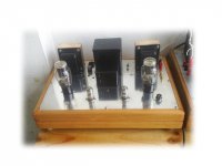
day said:this is my SE6B4G drive with 12AX7
Nice work,any chance of posting your schematic.Wouldn't mind using my Mullard m8137's with 2A3.
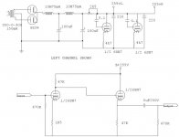
Grid leak resistor missing
Hi kianbach,
The grid leak resistor in the shunt regulator tube is missing. Have you check the voltage and current through the 4.7K cathode resistor. I suspect the 6SN7 regulator tube will become unstable or taking too much current.
You may check the original schematic.
Johnny
Hi kianbach,
The grid leak resistor in the shunt regulator tube is missing. Have you check the voltage and current through the 4.7K cathode resistor. I suspect the 6SN7 regulator tube will become unstable or taking too much current.
You may check the original schematic.
Johnny
Re: Grid leak resistor missing
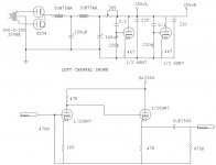
Thanks for pointing that out.I have put 220k gridleak resistors in but I drew the schematic in a hurry to post it and forgot to draw them.Will post the revised version later.
kmtang said:Hi kianbach,
The grid leak resistor in the shunt regulator tube is missing. Have you check the voltage and current through the 4.7K cathode resistor. I suspect the 6SN7 regulator tube will become unstable or taking too much current.
You may check the original schematic.
Johnny
Thanks for pointing that out.I have put 220k gridleak resistors in but I drew the schematic in a hurry to post it and forgot to draw them.Will post the revised version later.
kmtang said:Hi Kianbach,
That looks better. I would say you could try to use oil capacitor for the power supply. You could use 22 to 47uF instead of 220uF. You can really tell the differences between electrolytic and oil capacitors in the PS.
Johnny
Thanks.I'm using 100uF GE Oil caps in the first section of the psu.Do you think that changing the 220uF electrolytics for 40uF Oil caps after the 2k5 trimpot will make a difference?Any other improvement suggestions are more than welcome.Had a hum prob but that turned out to be my PSE 2A3 amp.Using SE KT88 now and it's quiet as a mouse.
Re: REVISED SCHEMATIC
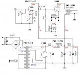
As it's drawn, the two 6SN7 shunt regulators, the two 220uF caps, and the two voltages 255vL and 255vR, are entirely in parallel and always at the identical voltage. If you added a second 2.5k pot and split the circuit apart just before the pots, you could have separate shunt regulators and capacitors for the left and right channels, effectively providing separate supplies for each channel. It kind of looks like that was the idea here, but that they ended up tied together for some reason.
Aaron T.
ETA: Like this:
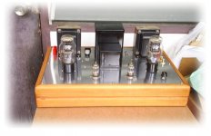
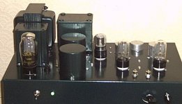
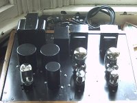
kianbach said:Here it is as it's built.Any suggestions/tweaks more than welcome
As it's drawn, the two 6SN7 shunt regulators, the two 220uF caps, and the two voltages 255vL and 255vR, are entirely in parallel and always at the identical voltage. If you added a second 2.5k pot and split the circuit apart just before the pots, you could have separate shunt regulators and capacitors for the left and right channels, effectively providing separate supplies for each channel. It kind of looks like that was the idea here, but that they ended up tied together for some reason.
Aaron T.
ETA: Like this:
Attachments
That was the idea.I am awaiting delivery of a set of 2k5 rheostats atm then I will be splitting the supply to provide better separation between channels.I loooove experimenting!!!
Next project is for my NOS Mullard ecc81 and ecc83 matched pairs.Any schematics would be gratefully received.Line preamps only no phono stage.
Next project is for my NOS Mullard ecc81 and ecc83 matched pairs.Any schematics would be gratefully received.Line preamps only no phono stage.
Hi Kianbach,
Surely, the last stage capacitor would have big impact on the sound effect. You may try to use the 22-33uF oil and polypoperlene capacitors. You would notice a big differences between electrolytic, oil, and polyproperlene types. Of course, if your pocket in deep enough, you may try to use those silver-in-oil capacitor which I believe it will be the BEST.
Have fun,
Johnny
Re: Re: REVISED SCHEMATIC
I've just rewired the circuit with a pair of 5k pots I had.WOW what a difference.Stereo separation is sooo much better.A lot less noise too.Thanks for the suggestion.
Next step= a pair of 32uF oil caps to replace the 220uF electros.
PS The b+ is now dead on 275v for each channel.
arteitle said:
As it's drawn, the two 6SN7 shunt regulators, the two 220uF caps, and the two voltages 255vL and 255vR, are entirely in parallel and always at the identical voltage. If you added a second 2.5k pot and split the circuit apart just before the pots, you could have separate shunt regulators and capacitors for the left and right channels, effectively providing separate supplies for each channel. It kind of looks like that was the idea here, but that they ended up tied together for some reason.
Aaron T.
ETA: Like this:
I've just rewired the circuit with a pair of 5k pots I had.WOW what a difference.Stereo separation is sooo much better.A lot less noise too.Thanks for the suggestion.
Next step= a pair of 32uF oil caps to replace the 220uF electros.
PS The b+ is now dead on 275v for each channel.
- Home
- Amplifiers
- Tubes / Valves
- Photo Gallery