Sure I'll put some stuff on
I'll put my project on that thread over the next
Couple of days
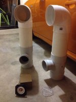
The pipe speakers were easy to make I've
Roughly worked them out to 13 liter
I've run them in on a class d amp haven't
Put them on the valve amp yet
I've started about 4 other projects in between
I'm just about ready to come back around
To it though
I'll put my project on that thread over the next
Couple of days
The pipe speakers were easy to make I've
Roughly worked them out to 13 liter
I've run them in on a class d amp haven't
Put them on the valve amp yet
I've started about 4 other projects in between
I'm just about ready to come back around
To it though
Attachments
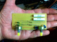
Just what the world was screaming for!
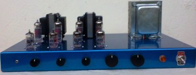
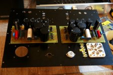
EL84 PP pentode output
Absolutely standard_ all 12AX7_ front end, direct coupled cathodyne, plus bass-treble tone controls.
All tubes are matched quads, brand new JJ's. The vendor made a really good job. Serious guy.
No sand, xcept for the PSU diodes, and the relay board bridge rectifiers.
Inspired by member Professor, from Russia, a relay board allows for -on the fly- change between 8 and 4 ohms OT speaker impedance termination. Besides, completely detach the speaker outputs, when you insert a Phone plug on the front. Works like a charm, with a nice clik!/clack! action.
The unit is still on the bench , for the measures & fine tuning. Coming soon.
Attachments
Nice build Jorge! It's underneath where your build quality really shines!
I'm of the opinion that we all strive for quality, quality of layout, engineering numbers (EG. 2W resistor for 800mW dissipation, et.al.)....genuine common sense approach towards creating a device.
I was berating someone on another thread for his sloppy work in creating a crossover..........I was dismayed by the "if it works, why would I care what it looks like?"
We all must strive for the un-attainable perfection in design & execution.
Now, esthetics,....???? I'm no artist.....& some create their own "interpretation", often failing. Beauty is truly in the eyes of the beholder.
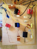
What do you think of such a cross-over, such as this?
______________________________________________Rick..........
I'm of the opinion that we all strive for quality, quality of layout, engineering numbers (EG. 2W resistor for 800mW dissipation, et.al.)....genuine common sense approach towards creating a device.
I was berating someone on another thread for his sloppy work in creating a crossover..........I was dismayed by the "if it works, why would I care what it looks like?"
We all must strive for the un-attainable perfection in design & execution.
Now, esthetics,....???? I'm no artist.....& some create their own "interpretation", often failing. Beauty is truly in the eyes of the beholder.
What do you think of such a cross-over, such as this?
______________________________________________Rick..........
Attachments
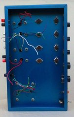
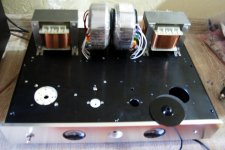
Hi Richard, well, certainly if where me, once debugged, I'll build a filter as compact as possible, but with an eye on the inductors mutual coupling. And the wiring, nice short, and ordinated, even if no one ever will look at it, and the thing remains hidden under tons of glass wool.. I'm that kind of maniatic..
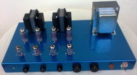
By the way , the amp still lacks an appropriate finishing (satin light industrial grey) on the OT and PT, and some lettering. Maybe also a more elegant on/off switch (within reason)
There is also a cage (still in the paint shop) made of perforated steel on the four sides, with a slim detail of Lapacho hardwood where it rest on the chassis.
Last edited:
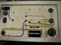
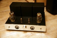
EF6 driver, EL3N SE
Hi,
Just finished. New look (this time no "box") thanks to a friend of mine.
It is an EL3N Single Ended with a EF6 triode connected driver. PSU and amplifier on separate chassis. Chassis both plywood, no metal parts used. Earth/ground consists of a 1mm2 silver wire..
Sound is very much okay. I tried both EL3N connected in triode and pentode (1.3W vs 4.5W) and do not understand why some people dislike pentode connection.. ;-)
Was a battle to get the parts in the small space.. but managed..
Attachments
Hi,
Just finished. New look (this time no "box") thanks to a friend of mine.
It is an EL3N Single Ended with a EF6 triode connected driver. PSU and amplifier on separate chassis. Chassis both plywood, no metal parts used. Earth/ground consists of a 1mm2 silver wire..
Sound is very much okay. I tried both EL3N connected in triode and pentode (1.3W vs 4.5W) and do not understand why some people dislike pentode connection.. ;-)
Was a battle to get the parts in the small space.. but managed..
hello ,
very nice build
")
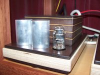
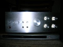
Harmon Kardon A 401
I bought this amp in 1976. I bought it and a pair of advent loudspeakers. Got the amp for $199 marked down from $299. A few years later I sold it to a friend who later moved out of Toledo. Last Christmas he came back to town after fifteen years and returned the amp saying it was dead. I checked the voltages and they seemed fine. So I hooked up a CD player and had a listen. Dirty pots, which a good cleaning took care of. A new power lamp and it seems fine. It's amazing how good it sounds for a '70s transistor amp.
Now if I could only remember what happened to my little Stromberg Carlson?
Attachments
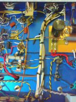
What do you think of such a cross-over, such as this?
How does it work? The wide spacing will certainly reduce unintended coupling.
In general rules Mr. Ellis, if you ask opinions about aesthetics in this topic, I must say that it seems to me that very cute cross over.Nice build Jorge! It's underneath where your build quality really shines!
I'm of the opinion that we all strive for quality, quality of layout, engineering numbers (EG. 2W resistor for 800mW dissipation, et.al.)....genuine common sense approach towards creating a device.
I was berating someone on another thread for his sloppy work in creating a crossover..........I was dismayed by the "if it works, why would I care what it looks like?"
We all must strive for the un-attainable perfection in design & execution.
Now, esthetics,....???? I'm no artist.....& some create their own "interpretation", often failing. Beauty is truly in the eyes of the beholder.
What do you think of such a cross-over, such as this?
______________________________________________Rick..........
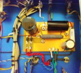
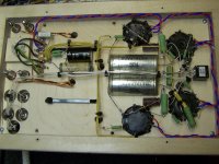
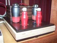
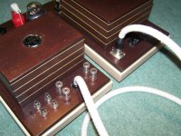
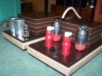
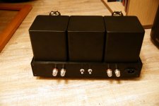
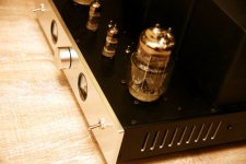
after the mock up amplifier, which was posted there earlier, my first tube amp ever approaching the finish line - so its 6C33C based on simplex schematic - dual mono with dual psu for each. For driver i plan to use ECC99 or cheap 6n6p (needs heater rewire) . Behind small tubes you can see bias adjustment pot.
For driver stage i use 415V PSU with CRC filter and for output 205 V psu with CL(1H per channel) CRC filter and approx. 230-260mA per Tube. No exotic parts- Yageo El.caps + bypass. MUR 4100 diodes, ALPS 50K pot, Vishy resistors. Indel (poland) output and power transformers. Meters from ebay ( rebuilt as voltmeters to meter voltage drop across 10R in psu- full scale 4V=400mA ) with blue led back-light. Apem toggle switches. Silver plated binding posts and rhodium palted RCA from Diyaudio member. After completion of all small things i will show you internal pics. Probably should have holes in power transformers cover for cooling. Enclosure from ebay with large holes CNC machined locally.
its Heavy and Hot !
some pictures attached.
Attachments
Last edited:
after the mock up amplifier, which was posted there earlier, my first tube amp ever approaching the finish line - so its 6C33C based on simplex schematic - dual mono with dual psu for each. For driver i plan to use ECC99 or cheap 6n6p (needs heater rewire) . Behind small tubes you can see bias adjustment pot.
For driver stage i use 415V PSU with CRC filter and for output 205 V psu with CL(1H per channel) CRC filter and approx. 230-260mA per Tube. No exotic parts- Yageo El.caps + bypass. MUR 4100 diodes, ALPS 50K pot, Vishy resistors. Indel (poland) output and power transformers. Meters from ebay ( rebuilt as voltmeters to meter voltage drop across 10R in psu- full scale 4V=400mA ) with blue led back-light. Apem toggle switches. Silver plated binding posts and rhodium palted RCA from Diyaudio member. After completion of all small things i will show you internal pics. Probably should have holes in power transformers cover for cooling. Enclosure from ebay with large holes CNC machined locally.
its Heavy and Hot !
some pictures attached.
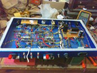
Very nice. Very clean and professional looking. What's it sound like?
Thanks , yes, a lot of unconventional solutions was needed to avoid making any extra holes through the chassis upper plate. I'm proud that the unit, that features 12 volt AC heathers throughout, has totaly inaudible and practicaly unmeasurable hum.Mosquito: very smart looking build.
Thanks , yes, a lot of unconventional solutions was needed to avoid making any extra holes through the chassis upper plate. I'm proud that the unit, that features 12 volt AC heathers throughout, has totaly inaudible and practically unmeasurable hum.
Congratulations co-forum friend. The look is nice, prof and handsome. I understand the troubles you had there for get good parts. I build a similar circuit in the 71th year when Galli hnos were there and had good parts for sale.
Hi Dady, well, fortunately in Our country, we still can resort to some good custom made iron, made by old dudes that KNOW, but we really have had a hard time to found good caps, decent potentiometers, and the kind of elegant fasteners you can found overseas. And forget about these fancy modern solid state components, the other forumers use to get the most from the beloved tubes..I understand the troubles you had there for get good parts.
- Home
- Amplifiers
- Tubes / Valves
- Photo Gallery