
zxx123,
Simplest and best are not always compatible! Your attached EL34 circuit looks OK, but you ask for 6L6, and replacing by 6L6s would slightly strain the concertina phase splitter, as a 6L6 would require about 2x the grid signal. Very generally, stay away from ECC83 (12AX7) in this sort of circuit - regular members will by now get tired of this advice from me. Also stick to UL, not pentodes.
I have an alternative circuit for you but can append that only later (bed time here!) Can you deal with an extra tube? My set-up would use EF86, ECC81 (12AT7) and 2 x 6L6GC.
Here's a good link for quite a few commercial amps schematics, take your pick from Heathkit, Eico, Mac....
http://www.one-electron.com/FC_Consumer.html
http://www.one-electron.com/FC_Consumer.html
zxx123,
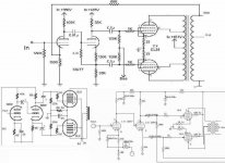
To fulfil a promise, I am going to try and attach a circuit that I have found to give quality response but is quite simple and trouble free. It can be improved, but that is a subsequent action. I apologise if the quality is poor; I had to re-copy it re-scanning - some wicked gentlemen came and collected my PC with un-backed-up info on together with other possessions a few weeks ago while I was out.
For the stability of any circuit with feedback the characteristics of the output transformer is of prime importance. Mine was self-designed with a primary inductance of 60Hy and leakage inductance of 18 mH (measured in the usual way). But interwinding capacitance also plays a role.
I am not going to extend this to an unreasonable length now; if you are intersted at all kindly indicate and I can pass on comments on testing etc., depending on your expertise.
Regards
I share Hacknet's recommendation, but found this slightly less critical.
Johan Potgieter said:Sorry, zxx123,
The info block indicates that the picture exceeds the allowed info content. I will investigate and post later.
Regards
Thank you guys.
@Johan, I hope you will not forget the promise.
")
That seems to have worked. You will notice that the #marked capacitors govern feedback stability with a given output transformer - and I have no way to tell what you will use. An oscilloscope and square wave generator will be necessary (ideally essential with any amp one builds). But as said, we can go into that should you be interested in this circuit. BTW input sensitivity is about 200 mVrms
Regards.
Regards.
Returning to this after a few days, I notice that there has been a few downloads. It may thus be prudent to supply some information inadvertently omitted - for that I apologise.
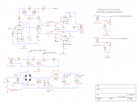
Main omitted further spec. is for the output transformer: I tested with a 7K primary with 25% G2 taps. Up to 8K will not make much of a difference. Taps at 33% still OK, going to 43% (more generally available) will limit maximum output power to about 23W. The 270 pF compensating capacitors might need adjustment accordingly. (But h.f. stability, as was previously stated, involves the whole transformer and needs to be correctly compensated for each brand.)
Perhaps further, the 340 ohm 6L6 cathode resistor is in fact 2 x 680 ohm 5Ws in parallel. Some believe in individual resistors for each 6L6 with some justification. Perhaps I have been fortunate never to have encountered 6L6s differing substantially. IMO the extra time constant poses more of a difficulty that a slight dc in the OPT. The large bypass capacitor affords some tendency to imitate fixed bias conditions with improved linearity during short bursts of music , as would larger values for the main power supply filter capacitors. (Not to advertise, but JJ makes a useful 100+100uF/500V component.)
Lastly the 100 pF input bypass cap is there in case of adverse r.f. conditions. It could well be decreased or omitted, depending.
Navin,
Since I have submitted an entry level design of my own it probably does not behove me to criticise that of others. But since you put the question, a few (respectful) general ideas regarding the amp on the site you quoted:
1. My usual comment regarding resistance against negative feedback is that it is not supported by theory and a vast field of practice. "I do not like feedback" is an individual choice to which a person has the fullest right, but that impression is often the result of efforts to clean up a poor design (not referring to this one specifically).
2. While I find the concertina phase splitter hard put to swing the total of 150Vpp odd that 6L6s would require with as low distortion as the long-tailed pair (LTP), it does not suffer from the disadvantages quoted in the mentioned article. The misperception that the outputs are unbalanced especially at high frequencies, simply because the internal resistances differ, is a common one. Since the same current flows through both the cathode and anode (total) impedances, the output voltages will remain the same as long as these impedances (i.e. including that of the power tube inputs) are the same, regardless of frequency.
3. In the given design I wonder why the anode resistors are so low. Quick calculation shows that the anode dissipation will be close to maximum (exact current/voltages are not given) - which is 3.5W for both triodes according to my data. Also, my feeling is that the advantage of a CCS for the LTP is sometimes overrated. I did not check, but what is the frequency response of the given IC? All that is required are equal output voltages from both triodes over the audio spectrum - if this can be achieved with a common cathode resistor, why go to the extra trouble?
I would repeat that these comments are intended as guidance for those in need of such, and not to disparage any particular individual.
Regards.
johan; thanks for the circuit. I have a couple of comments. It is the classic 5-20 circuit. The bypass cap on the common output tube cathode resistor is WAY too large. When the amp is cranked up the cathode current increases; and the cap charges up; altering the bias. The huge cap takes a long time to recover; something on the order of 22-47 uF is about right. Similarly the coupling caps to the output control grids are also too large; low frequency signals that would saturate the OPT will pass thru those caps. I would run .22 uF and drop the grid resistors to 100K.
Thanks for your interest and comments.
The large 6L6 cathode capacitor is an attempt to go nearer a fixed bias condition under normal music signal circumstances, in which case slightly increased and more linear output peaks can be expected. (Infinite capacitor = fixed bias.) With a time constant of about 0,2 Hz you should find very little increase in bias voltage on there. (With component physical sizes these days it is even practical to use a 10 000µF cap.)
By changing the 6L6 grid coupling time constant you may compromise l.f. stability. Signals that would saturate the OPT should not be there in the first place, also depending on the OPT; they should be taken care of by an earlier cut-off. But if you fear that or a particular build shows dangers, by all means. Only by decreasing the 6L6 grid resistors you also shift the dynamic load lines of the phase inverter into a region of greater non-linearity; it already has to cope with quite a high output signal.
Those my reasons for the chosen values, you may of course experiment!
My recommendation is the E-Linear circuit developed by Bandersnatch. See thread linked below Post #4. The circuit is shown with 6AU6 drivers but when I built it I used a pair of 6AC7's. I have used this design with 6L6GC as well as EL34s and KT77s. It is not only simple but capable of top flight sonics.
http://www.diyaudio.com/forums/tube...-build-25-30-wpc-push-pull-amp-need-help.html
http://www.diyaudio.com/forums/tube...-build-25-30-wpc-push-pull-amp-need-help.html
- Status
- This old topic is closed. If you want to reopen this topic, contact a moderator using the "Report Post" button.
- Home
- Amplifiers
- Tubes / Valves
- What is Simplest and Best 6L6 PP circuit? (PK)