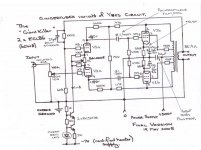
I have a little Push Pull Amp (ECL86) - the Output Transformer has 0-4-16 Ohm Secondary. By grounding the 4 Ohm output I can wire the 0 and 16 Ohm lines into the cathodes of the output tubes for a bit of cathode balanced feedback .
My concern is that I have 4 Ohm speakers (actually 6 Ohm nominal) and will therefore have the speaker connected across one cathode feedback winding ONLY. Transformer Theory says that this should'nt matter as the speaker load will be reflected equally to the other side. Unfortunately transformers are NOT ideal components and so I don't know if the theory is good enough especially since the particular output transformers in question are very "middle of the road" with regards quality.
Anyone tried this. Is it OK to wire the speaker load to just one side of the secondary when also using it for cathode feedback to the output stage? Anyone want to hazzard a guess ?
Any feedback (pardon the pun) gratefully received.
Cheers,
Ian
Yes, you can do it. Your more likely problem is instability. I recently built a PP amplifier with an ultra-linear output stage having cathode feedback, but once I wrapped a little bit of global feedback around the amplifier, achieving stability became tricky. I had 6dB of CFB, but you are likely to have rather less, so stability might not be as tricky. Check your 10kHz square wave response...
The trick to stabilizing is to run the feedback symmetrically from the 16 and 0 taps.
In reality, this connection is of little benefit for triode and UL- what you gain in distortion reduction from the few dB of feedback, you lose again since the driver stage has to (roughly) double its swing. For pentode stages, there is some net benefit in source impedance reduction.
In reality, this connection is of little benefit for triode and UL- what you gain in distortion reduction from the few dB of feedback, you lose again since the driver stage has to (roughly) double its swing. For pentode stages, there is some net benefit in source impedance reduction.
Thanks Guys,
SY - Point taken BUT it was actually damping factor I was after.
The amp in question is my variation on the Yves Monmagnon little ECL86 Amp (see the "Hey Planet-10" Thread) - its on the edge of serious gorgeousness with just a little bit of bass boom ONLY evident with some music selections. My variation already runs 12dB balanced shunt feedback from the output tube anodes and 20% Ultralinear to the screens. I wanted to reduce global feedback (currently about 9dB ) to get the "liveness" and imaging improved. However I'm pushing the limits of the diff amp driver already (and sensitivity is not great) so its a major redesign or just enjoy it "as is". I can cure the bass boom with a bit more global feedback BUT this compresses the image and makes the amp subjectively slower. It was better in this regard when I was running only 6dB global feedback. It is the speed, attack and "liveness" this little amp I've found so impressive and I'm convinced this is due to the low global feedback.
For 8W per channel it remains a "gaint killer" amp. I thought if I could just finness it that last little bit it would make the best "newbie" amp going, after all requests for the best amp for a beginner to build seems to be VERY common. It leaves my EL84 "Morgan Jones" Ultralinear Amp for dead and perhaps more surprisingly gives my 20W per channel 845 SET serious competition.
I intend to rebuild the "Morgan Jones" 6DJ8 /EL84 amp to this circuit by replacing the 6DJ8 (CC/split load inverter) with a 12AX7 (Current Source biased diff amp) as a final test of the schematic and then perhaps publish it here. The output trannies on the MJ amp are far superior and have 43% UL rather than 20% - That MAY be sufficient to achieve my ends.
BTW you probably already know BUT screen resistor value is critical in stabilising Ultralinear connected output tubes i.e. Its grid stopper function is more important than its g2 dissipation limiting function.
Cheers,
Ian
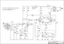
Did the final fine tune last night. I managed to get rid of the slight bass boom and the slight lack of "liveness" by decreasing local balanced shunt feedback - the 15K shown below (final value) was 2x 33K in parallel ( = 16K5) so the adjustment required was tiny. I found the same thing with the global feedback and the 100K value. 82K was too much 120K was not enough.
So for your edification here is the final ECL86 version. Its final because I've screwed the base on.
Ther must be 1000's of ECL82 and ECL86 Amps out there which could benefit from this circuit change.
Will let you know how the 12AT7 EL84 version goes. Will start it this weekend.
Woops who changed the image rules - back to photoshop to get it down to less than 1000 x 1000
Cheers,
Ian
Attachments
One more evenings fiddling:
The balanced shunt feedback is nowhere near the 12dB stated above. Confirmed by Zout measurements with it in and out. The feedback voltage is being divided by the rp of the diffamp tubes.
Came down to an exersize in juggling the 15K which sets local feedback and the 100K which sets global feedback. The more local the less global required.
I found 2 "sweet spots"
1) 47K for local and 150K for global
AND
2) 27K for local and 100K for global
Settled on the 2nd of these 27K/100K after some further listening tests. The amp has now gone to its new owner - my cleaning lady to run her Polk R5s.
As far as rebuilding the Morgan Jones EL84 Amp to this schematic goes it means that I'm stuck with 12AX7 for the diff amp - I NEED that high ra to maintain local feedback levels.
My view after all these experiments is that you need about 6dB of local feedabck to push the output tube/transformer combination one octave lower (lower rp to drive primary inductance better) and one octave higher higher (lower rp drives leakage inductance and primary capacitance better). After that the sonic improvements are due to the current sourced diff amp front end AND perhaps more importantly the reduction in required global feedback.
P.S I ditched the original "Ring of 2" current source on the diff amp and replaced it with the Cascode Current Source, LED referenced, shown in the schematic above and got noticable improvement. I also tried dual LED reference in the CCS and found NO benefit. While this allowed doubling of the emitter resistor, by the time you multiply the emitter resistor by hfe of the bottom transistor and then by the hfe of the top transistor you are already passed the point of the Zout being dominated by device capacitance and so dual series LEDs for a higher reference voltage are of no benefit.
Cheers,
Ian
Update:
The Morgan Jones Ultralinear Amp is rebuilt to this circuit.
I found that the local feedback set resistor can be made too large causing the 12AX7 to saturate/cutoff limiting the output power.
About 47K is the maximum value. Currently running with that resistor set to 39K and NO global feedback. Sound is stunning!!!
Zout is 1.5 Ohms, Low frequency corner (at 4 watts out) is below 24Hz at which frequency waveform distortion sets in due to transformer saturation and upper frquency -3dB point is above 100kHz.
Cheers,
Ian
Jaap,
My GUESS is yes. The difference with the ECL82 (6BM8) is that the triode section is more like a 12AT7 rather than a 12AX7 and rp is lower. This will divide the shunt feedback somewhat and so the cross coupling resistor in the shunt feedback will need to be increased to get higher feedback voltage. The current swing in the diffamp will then need to be increased to maintain the output swing into the output section grids. You might want to run the diff amp at higher current so that you can get this increased signal swing without cutting off the triodes. It will be a bit of trial and error to adapt it.
Proceed as follows:
1) Build up the circuit as shown but with 6BM8 and no global feedback.
2) Use a piece of wire with clips each end to short the shunt feedback cross coupling resistor (that is set the shunt feedback to zero).
Measure Power Out and Outout Impedance.
3) Remove the short from across the cross coupling resistor and adjust the value of that resistor untill Zout drops to approximately half the value measured above AND check that you can still get the same output power - if not it is probably the diffamp which is limiting signal swing, in that case increase the diff amp current a bit (adjust the emitter resistor on the bottom transistor down) until full output is restored and then go about 25% (minimum) above that current so there is a little headroom when global feedback is applied.
4) finally add about 6dB of global feedback - this can be judged by observing a halving of Output Impedance, and add the lag compensation cap across the feedback resistor for best 10kHz squarewave into dummy load.
Cheers,
Ian
 I hope that one the the well respected forum members will be faster than I am and reports his results here with the ecl82 in this design.

For general info,
This design has generated some interest on another forum (Audioasylum).
One of the VERY interesting variations being tried there is a cascode diff amp (high rp is advantagous to maintain shunt feedback levels) with 6V6 outputs. This one has sparked my interest and will put it on my list of projects to try it as time allows (6N1P for the cascode diff amp).
I have a couple of 120W 4 x KT88 Monoblocks to finish first.
Cheers,
Ian
gingertube said:This design has generated some interest on another forum (Audioasylum).
Got a link to the appropriate thread?
dave
What to do with no 4ohm leads?
I'd like to build the gingertube ECL86 amp, but using 8 ohm speakers.
In gingertubes original, the feedback is coming off the 4ohm leads on the output trans. I'd like to use the Edcor GXPP15-8-8K. If I switched to an 8k:8ohm transformer, what would need to change in the circuit? (if anything)
Thanks
netbug,
The shunt feedback will not change as the voltage swing at the pentode anodes does not change.
The voltage across an 8 Ohm load is however different from across a 4 Ohm load for the same output power. So the global feedback has to change.
We want the global feedback VOLTAGE to stay the same.
A bit of algebra.
Currently (4 Ohm load):
8 Watts into 4 Ohms (P=V^2/R) we get 5.657V RMS at secondary.
That 100K + 6K8 divider means we get
5.657 x 6K8/(100K + 6K8) = 0.36V RMS of feedback at that I/P tube grid. We want this same feedback voltage when taking the feedback from the 8 Ohm Tap.
With 8 Ohm Tap.
8 Watts into 8 Ohms we get 8.0 V RMS at secondary.
We don't want to increase that 100K feedback resistor since it is feeding the Miller Capacitance of the triode. We want to reduce that 6K8 instead.
So we want:
8.0 x Rx/(100K + Rx) = 0.36 V RMS
Cross Multiply to get:
8Rx = 36K + 0.36Rx
Gives:
7.64Rx = 36K
Rx = 4.712K
So replace the 6K8 with a 4K7 - That is all you need to do.
Cheers,
Ian
Hi Ian,
as a total newbie here - but with tons of vintage tube amps in my basement and all the NOS tubes u ever could dream of, i'm of course keen to learn if your nice concept spread above could fire up some of my goodies here.
From what i read so far, UL output stages benefit the most.
I currently try to refurbish, na - better to upgrade an old Pioneer SA 810. Unfortunately got no schematic, but since this one is point to point built, it should be easy to implement your design.
The diffamp uses 6AN8 which measure pretty low, so I'm thinking to swap for 12DW7 (availlable as ECC832 by JJ), using the AT-triode or the AX as driver. Any recommends?
greets
Verne
Attachments
- Status
- This old topic is closed. If you want to reopen this topic, contact a moderator using the "Report Post" button.
- Home
- Amplifiers
- Tubes / Valves
- Cathode Feedback from Secondary for PP Amp