Has anyone built this simple amp from Triodeels website? I'm in the middle of prototyping one channel to drive my TQWTL with TB W4-1052SA drivers. What happens if a bypass capacitor is added to the cathode resistor? What about RH circuit being added to driver tube? Thanks from a newbie...
Attachments
Sparky OR said:Has anyone built this simple amp from Triodeels website? I'm in the middle of prototyping one channel to drive my TQWTL with TB W4-1052SA drivers. What happens if a bypass capacitor is added to the cathode resistor? What about RH circuit being added to driver tube? Thanks from a newbie...
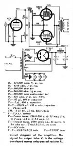
The circuit's bad enough as it is. Bypassing the output cathode resistor will make it into an SE amp with half the load resistance = low power output (probably around a quarter what it is with both tubes functioning properly) and high distortion (probably in the 15% range at full output).
I mean, look at the schematic. If you ground the cathodes to AC... no signal *at all* can get to the second 6BQ5...so wtf is it doing? Nothing!
To make this circuit actually work right, you need a CCS - they didn't have squalid state in those days, but nowadays a short negative supply (derived from the 6.3V heater winding) and quick IRF640-ish (or your favorite removed-from-scrap transistor or FET) current sink will make it run like the wind.
If you meant the 6C4 cathode...that can be bypassed without problem. Speaking of it, you can use a 6AV6 if you need more gain (a wise decision since this amp also has no NFB; in fact a pentode mode 6AU6 would be best).
Tim
Have a look at the Simple EL84 at http://diyparadise.com/simpleel84.html
This is an update of this kind of amp with a lot more info. It really does need a CCS on the cathodes of the outputs to get the phase splitting to work properly. (althou i still haven't figured how he is getting his bias with the CCS tail at ground).
John Swenson also has a version of this on AA, but with a trafo out front instead of a driver tube.
http://db.AudioAsylum.com/cgi/searc...sage=&sort=score&sortOrder=DESC&forum=tubediy
Me, i still think i'd use a CCSed long tailed pair up front.
dave
planet10 said:(althou i still haven't figured how he is getting his bias with the CCS tail at ground).
The bias is derived by the voltage drop across the CCS, since the CCS tail and the grids are at ground potential. If the CCS is programmed to draw, say, 80mA, the CCS will reach an equilibrium such that the voltage across the CCS will be such that Vgk allows 40mA through each valve for the given HT voltage (provided the valves are reasonably matched, if not, one will be slightly less and one will be slightly more). A negative supply is only needed if the CCS won't be happy operating with such little voltage across it (often the case with pentode sinks).
audiousername said:The bias is derived by the voltage drop across the CCS, since the CCS tail and the grids are at ground potential. If the CCS is programmed to draw, say, 80mA, the CCS will reach an equilibrium such that the voltage across the CCS will be such that Vgk allows 40mA through each valve for the given HT voltage (provided the valves are reasonably matched, if not, one will be slightly less and one will be slightly more). A negative supply is only needed if the CCS won't be happy operating with such little voltage across it (often the case with pentode sinks).
I understand the current part, but how is the grid bias set at 10.5 V? (i'm still lost with SS)... we drop 40 mA x 1.2R = 48 mV across the sense resisitor means that the CCS needs to look like 10.45 V/80mA ~ 131 R... how is this magic done? Is it just where things fall?
dave
The 1.2W resistors have nothing to do with the CCS, they are just there as a convenient way to measure the cathode current of each valve individually (by measuring the voltage drop across them). The actual current set resistor in this case is R1 in the circuit below:
http://diyparadise.com/yhlmccs.html
(you probably already knew this, but just in case...") )
)
Yes, at DC, the CCS may be equivalent to a 131W resistor, but to a signal, it appears to be a very much larger resistor.
You may be familiar with the fact that calculating Va/Ia for a valve is not a good approximation for the output impedance for a valve stage (particularly for pentodes). A similar thing happens here - it's just that Va/Ia is much smaller than the output Z of the circuit.
There's no magic here, SS or valve
http://diyparadise.com/yhlmccs.html
(you probably already knew this, but just in case...
)Yes, at DC, the CCS may be equivalent to a 131W resistor, but to a signal, it appears to be a very much larger resistor.
You may be familiar with the fact that calculating Va/Ia for a valve is not a good approximation for the output impedance for a valve stage (particularly for pentodes). A similar thing happens here - it's just that Va/Ia is much smaller than the output Z of the circuit.
There's no magic here, SS or valve
audiousername said:The 1.2W resistors have nothing to do with the CCS,....is much smaller than the output Z of the circuit.
I got all that, i'm just having trouble with how the grid gets 10.5 V negative to the cathode. In this case the CCS would have to convieniently look like a 130 ohm resisitor wouldn't it? What would you do if you needed, say 20V? set the CCS tail at -9.5 V? (i can see this working if the CCS is dropping V like a 130 ohm resisitor)
dave
planet10 said:
I got all that, i'm just having trouble with how the grid gets 10.5 V negative to the cathode. In this case the CCS would have to convieniently look like a 130 ohm resisitor wouldn't it? What would you do if you needed, say 20V? set the CCS tail at -9.5 V? (i can see this working if the CCS is dropping V like a 130 ohm resisitor)
dave
Ahem ! I beleive that the name "current source" is somewhat disturbing. Current regulator seems more appropriate, but ...
A current regulator is a two terminals unit in wich the current remain constant what could be the voltage accross it.
With two practical limitations, the first being that a minimum of voltage exists (no voltage, no current) and that it does not destroy the regulator.
A "true" source may then be seen as a voltage source in serie with a current regulator, the value of the voltage source does not matter (within some limits as explained above).
Now, put a current source between the cathode and the ground of a tube, and tie its grid at ground. The current in the tube will remain unchanged WHATEVER the voltage you apply to the plate because the voltage accross the current source will increase (or decrease) to maintain the current constant, and since the current source is tied between the grid and the cathode, it adjusts the bias automatically.
Yves.
hi dave
well, look at it this way.
we want to do this. we want to set the ccs to 80ma with the idea that each tube conducts 40ma. that's why the 1.2ohm (1ohm is just fine) is useful for measuring voltage then calculating current.
after adjusting with a pot for 40ma each tube, we now hv 40ma flowing each tube! wonderful! you can now measure the plate voltage as well right?
if you look at el84 curves, with the current plate voltage and 40ma, you hv the grid-cathode voltage. ta da!
donjuan
planet10 said:
I understand the current part, but how is the grid bias set at 10.5 V? (i'm still lost with SS)... we drop 40 mA x 1.2R = 48 mV across the sense resisitor means that the CCS needs to look like 10.45 V/80mA ~ 131 R... how is this magic done? Is it just where things fall?
dave
Simple: current sinks (there's your word, Yves
) are non-ohmic devices. Just like zeners, which have a constant-voltage characteristic, and tubes which have a 3/2 power or constant current characteristic.Tim
Yvesm said:and since the current source is tied between the grid and the cathode, it adjusts the bias automatically.
DonJuan said:if you look at el84 curves, with the current plate voltage and 40ma, you hv the grid-cathode voltage. ta da!
OK...
The current parts i get...
How the voltage gets to the appropriate value still seems magic to me.... guess i'll just have to build it and experience it
dave
I really appreciate all this great info. I definitely will want to try the CCS version. But first I need to debug my prototype. It plays, not as loud as my SE EL84/6EU7. It also seems to have a couple bugs to work out. I put a switch in series with the 100k treble pot. I didn't expect to find the volume drop to 0 as the R dropped past 1/2 way(treble pot). Even worse, there was initially an occasional pop at full volume. I also noticed with the tone pot dialed low, the B+ voltage went sky high! (500V  ) I also noticed only 7 volts on the 120 ohm cathode resistor I used. Maybe my supply lacks steam? 250V present less the bias voltage. Will debug later,....again thanks
) I also noticed only 7 volts on the 120 ohm cathode resistor I used. Maybe my supply lacks steam? 250V present less the bias voltage. Will debug later,....again thanksMagic resistor
Hi Dave,
It is magic !!
You may look at the CCS as a "magic resistor" wich adjust itself to maintain a constant current THROUGHT it whatever could be the voltage ACCROSS it.
In this context (CCS in the cathode) the voltage accross the "magic resistor" will be exactly the bias needed by the tube for it passes the current you wish.
The CCS does not know how much voltage it must set, but the tube KNOWS !
Does this help ?
Sparky,
Have a clean short wiring and try to use grid stoppers.
Yves.
Hi Dave,
How the voltage gets to the appropriate value still seems magic to me.... guess i'll just have to build it and experience it
It is magic !!
You may look at the CCS as a "magic resistor" wich adjust itself to maintain a constant current THROUGHT it whatever could be the voltage ACCROSS it.
In this context (CCS in the cathode) the voltage accross the "magic resistor" will be exactly the bias needed by the tube for it passes the current you wish.
The CCS does not know how much voltage it must set, but the tube KNOWS !
Does this help ?
Sparky,
your PB looks like parasitic oscillations.It also seems to have a couple bugs to work out. I put a switch in series with the 100k treble pot. I didn't expect to find the volume drop to 0 as the R dropped past 1/2 way(treble pot). Even worse, there was initially an occasional pop at full volume. I also noticed with the tone pot dialed low, the B+ voltage went sky high!
Have a clean short wiring and try to use grid stoppers.
Yves.
Re: Magic resistor
Yes thanks... i was getting the idea from the 2 earlier posts, but yours is the icing...
dave
Yvesm said:You may look at the CCS as a "magic resistor" wich adjust itself to maintain a constant current THROUGHT it whatever could be the voltage ACCROSS it.
In this context (CCS in the cathode) the voltage accross the "magic resistor" will be exactly the bias needed by the tube for it passes the current you wish.
The CCS does not know how much voltage it must set, but the tube KNOWS !
Does this help ?
Yes thanks... i was getting the idea from the 2 earlier posts, but yours is the icing...
dave
I think you are getting it, but if the horse isn't totally dead I can whip a little more:
> How the voltage gets to the appropriate value
Forget the current source.
Build a cathode follower with resistor load. Say +300V on the plate, grid resistor to 0V, and a 50K resistor to a -1,000V supply.
As a rough guess, tube grid-cathode voltage is "small" compared to 1,000V. So the resistor sucks 1000V/50K = 20mA of current from the tube.
Now we look on the tube curves. At ~300V, we might find that it takes -20V grid-cathode to pass ~20mA. That is our next approximation.
We are close to 280V and 1020/50K = 20.4mA. Squinting at the tube curves, our new guess is -19.5V grid-cathode. We could now try 280.5V and 20.39mA, but clearly the tube WILL find an operating point "about" 20V grid-cathode.
And if we change the 50K to 100K, "about" 10mA, the tube will find a new operating point "about" -25V grid-cathode.
Or consider the good old Cascode, beloved of TV tuner designs. The lower tube is biased to 10mA-1mA (variable to adjust RF gain). The upper tube is (sometimes) fixed-biased with +100V on its grid. Its cathode will find an operating point: maybe -1V (+101V) at 10mA, -10V (+110V) at 1mA.
The sand-state current-limiter will do the same thing, but without the extra 1,000V or 100V voltage drop. For (almost) any current we set the CSS at, the tube will find its grid-cathode voltage that will (at that plate/screen voltage) pass the current being sucked through it.
Of course the only reasons to do the "Self Inverting" trick are to use a cheap push-pull transformer and power filter instead of beefy SE iron and filter; and to increase the tube-count to look good on the name-plate. You could get 6 Watts easy with one 6L6, or by beating the heck out of one 6BQ5. But the push-pull savings might pay for the extra tube, and "8 tubes!" looks better than "7 tubes!"
Re: just to be sure I get it right...
For a CC sink, as in this thread, "In" would go to the sense resistors and "Out" to ground (or V-).
For a CC source, "In" to V+, and "Out" to the circuit.
Sparky OR said:using the LM317 CCS, which leg is ground? Vin or Vout...a 50 50 shot, and I'm sure it's obvious to most.
For a CC sink, as in this thread, "In" would go to the sense resistors and "Out" to ground (or V-).
For a CC source, "In" to V+, and "Out" to the circuit.
- Status
- This old topic is closed. If you want to reopen this topic, contact a moderator using the "Report Post" button.
- Home
- Amplifiers
- Tubes / Valves
- 6W Self Inverting 6BQ5 Amp