A big vote for split bobbin, and a lack of enthusiasm for shielded torroids. Even with the shield, a torroid will not provide the equivalent high insulation resistance or low capacitance that a split bobbin will. And you always have the challenge of lead exit with the torroid - no matter what you do you have to get those leads past the shield, which will crowd into the other winding if you have evenly distributed windings (which is really one of the few purposes to torroids, low magnetic strays).
I digress. There is an additional check I would recommend, even when using split bobbin. Each primary lead has some capacitance to core/ground, whether it be large or small. There will usually be one of those leads which has a slightly higher capacitance to ground. It is desired to have the lead with the highest capacitance connected to neutral, to reduce mains induced leakage current to ground. Fortunately, the test is quite easy.
Connect core to secondary. Core to be ungrounded for the test. Energize the primary with line voltage. Measure AC volts with a decent high impedance meter (no VOM's or wiggys) from core to earth ground/3rd prong. Switch primary lead polarity on xfmr, and repeat test. One of those measurements will almost always be greater. The primary lead polarity with the greatest measured voltage is the one whereby you have applied the hot to the highest capacitance lead. Therefore, you have identified the highest capacitance lead - mark this lead as the one you want to connect to neutral, not hot.
Some rapid measurements:effective capacitance from primary to secondary.
1.) custom wound 2x15V -2xSM75- : 130pF, 160pF
2.) Indel 2x17V toroid: 440pF, 370pF
3.) MerkelBach split bobbin 15V-0-15V: 90pF !!
Member
Joined 2009
Paid Member
DIY Schematic
Hi Rod,
I'm toying with the idea of making my own pcb for a filament heater in order to meet certain requirements for parts, size etc. It would surely be easier to use yours and I might still go that route - it's early days...
But if I want to DIY this thing, is there a schematic that you have released for public use - i.e. which post should I go look at for a useable circuit even though it won't have all the benefits of your latest but proprietary circuit ?
I am a little surprised by how the R1,R2 resistor types can change the sound in Rod's kit. The resistors is vitreous wirewound type, 0.68ohm in R1/R2 position. they are connected in parallel to give around 0.33ohm in my GM70 kit version.
I paralleled 8 x 2.7ohm (2W, carbon film) resistors and installed into the R1/R2 position. there is an immediate discernible shift in the sound. Can u imagine this? a current sensing resistor for a filament reg supply, and the type of resistors make a difference!
The carbon film gives more lush to the vocals. However, i still prefer what is provided in Rod's kit. Carbon film softened the bass lines, and the upper frequencies sounded a little fuzzy. anyone here tried carbon film in r1/r2 and like them?
someone here has replaced the tiny cap C3 with physically larger ones. due to the space contraint on the pcb, some members here soldered wire leads out from the PCB and then soldered the larger caps to the two wire leads. This effectively lengthen the the cap leads, and it has no real support ; the cap is 'dangling' in the air. I have a feeling that this may not be a desirable change since the cap need to be small with shortest lead possible, base on the fact that it is a compensation cap.
I'm seriously wondering to what extent tweaks in Rod's boards are audible, and to what extent users are hearing what they think should be happening, like carbon = warmer etc. Believe me, I'm open to either interpretation. In terms of audibility I believe I hear quite audible differences in the cathode resistor in filament bias - I tried numerous ones and settled on some discontinued Dale wirewounds I got on ebay. I disliked thick film ones in particular, and I thought I preferred the vitreous enamel ones (e.g. the green Welwyn ones but also other varieties) to the white ceramic and alu clad ones. But having said that, I might not have heard any difference if I'd listened blind. My expected rank order would have been to prefer vitreous to alu clad and ceramic, so was I hearing what I expected to hear? Against that, I expected the thick film to sound the best and I was surprised that they didn't, so it seems that my ears have the ability to "think" for themselves and hear what's actually happening.
I can't report on components in Rod's boards because I haven't yet done any critical listening. I know the Danes have and reported hearing differences in the caps and set resistors. It's a bit more complicated with me since I still use Rod's original circuit, though I also have his new boards as well. At some point I'll have to see if I can hear any differences.
But I think we're often in the situation where we have to A-B different parts and make a choice. And I wouldn't like to say for sure now much we actually hear differences and how much we think we hear differences based on what we expect to hear. I'm open to either interpretation or a mixture of both. The one thing I'm sure of is that it's very easy to exaggerate the scale of changes and say "much better" etc. I'm pretty convinced that changes like this are a lot smaller than we think they are.
I quote myself on the ''upgrade of R1 and C3 issue''.
I have upgraded with these parts. Here in Denmark we are (at least) two Tram II owners, and when I bought these parts I bought them for both myself and Bjarne (''Beardman'' here on diyaudio). I installed the parts, listened and heard a difference that was quite easy to hear. I did not tell Bjarne what I heard, so it was interesting to compare our experiences after upgrading R1 and C3... Bjarne heard exactly the same difference / improvements.
That is good enough for me")
However, I do agree that in hifi we often tend to put the differences under the microscope, and subjectively small differences are passed on as substantial. For instance many of my audio-buddies tell how big difference in sound their very, very expensive power cords make. Personally I hear just very small (if any) differences on power cords, so that is not where I spend my money on my system...
I have upgraded with these parts. Here in Denmark we are (at least) two Tram II owners, and when I bought these parts I bought them for both myself and Bjarne (''Beardman'' here on diyaudio). I installed the parts, listened and heard a difference that was quite easy to hear. I did not tell Bjarne what I heard, so it was interesting to compare our experiences after upgrading R1 and C3... Bjarne heard exactly the same difference / improvements.
That is good enough for me
However, I do agree that in hifi we often tend to put the differences under the microscope, and subjectively small differences are passed on as substantial. For instance many of my audio-buddies tell how big difference in sound their very, very expensive power cords make. Personally I hear just very small (if any) differences on power cords, so that is not where I spend my money on my system...
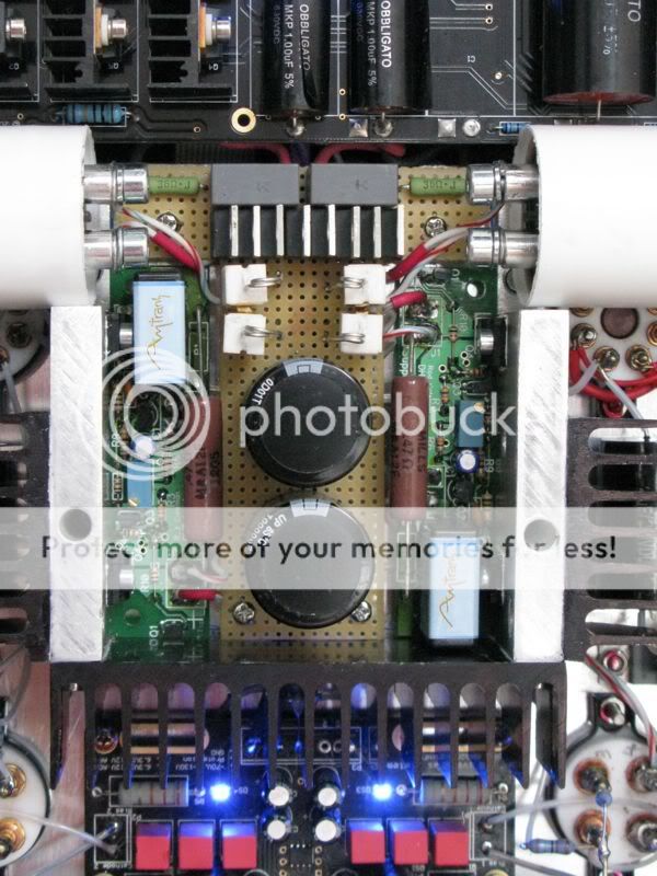
I have now updated C3 and R1. For C3 I have choosen Amtrans AMCH mylar caps... Good sound, decent price, not that big so they can actually fit, finally they are spec'ed for high temperatures. For R1 I have choosen 12W Mills wirewound, they sound great and have a big surface area to dissipate the heat from so they don't run so hot.
When not using R2 there is actually decent space for the caps, so the installation can be quite clean as seen here
Last edited:
It's convenient to use polycarbonate caps - they're small. I don't see them about much but they used to be plentiful. Remember those small green and silver ones with the legs welded on either side? You can see them in this link.
Polycarbonate Capacitors
Polycarbonate Capacitors
Component changes? it's a good question, and the answers are not entirely able to be explained, but I can offer some thoughts about real physical effects that may be helpful:
1. Magnetic materials. Many resistors, including the normal wirewound (R1, R2) and carbon film (all the others in the standard kit) have steel in the end-caps or the leads. If the regulator is near any transformers in an amplifier, some heightened magnetic coupling is possible. If you have a very transparent system, and there are possibly some stray fields near the regulators (a densely packed design like the TRAM is a good example), then the chances are that using nonmagnetic wirewounds will improve the sound.
2. current noise. The sense resistors R1 R2 carry the filament current. But the filament current flows in the same conductor (the filament substrate) as the music signal, no noise in the filament current will directly impose on the music. The current-noise of resistors is well-known to vary between resistors of different constructions - see for example:
https://dcc.ligo.org/public/0002/T0900200/001/current_noise.pdf
The crucial fact is that we are getting 1.25A-worth of current noise (300B filament) imposed on the few-mA of music signal current - so a small change might well be heard.
I think that most folk like the low DIY price of my regulators, so I prefer to ship them with types that sound good, if not the ultimate. Changes to resistors are system-dependent and very much a question of taste - so please experiment and try other parts - providing R1 and R2 have the same level of power handling.
The obvious choice for the small resistors would be Tantalum film - a nice nonmagnetic design favoured by Kondo-san, among others. I have not checked availability of these yet. It would be a very-high-resolution system that could pick out differences of that kind - the small resistors[ R3 .. R11 ] do not have a strong influence on the output current.
Summary: Try non-magnetic wirewounds at R1 as the most likely tweek. Then go after the capacitor. Try the Amtrans that Morten likes.
Tantalum for the other resistors is strictly for the adventurous...
.
Hi Rod
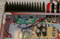
I thought I'd post this here instead of emailing as it might benefit some readers. I've got a couple of queries on the boards I'm using with sv572/sv811. I changed my original RS 2x9v 100va frame to a toroid as it was buzzing loudly. I changed to an airlink toroid 2x9v 120va. This allows best part of 9v@7A for each regulator.
It gets very hot, 60+celcius(by my rough dmm thermometer). As the transformer for sv572 was not mentioned in the app. notes I was kind of working in the dark, but correspondence with Rod enlightened somewhat. It seems I need 3 times the end current at the transformer to start with. In my case thats 12amps, for a 4 amp sv572. I hope I'm understanding this correctly. I'm currently looking at a 2x9v frame 200va.
Notwithstanding the transformer issue the results are superb as I've lost most of the noise from the amp. But.... the barrier diodes, MBR1045, are getting really toasty, 105celcius(by the same dmm as mentioned before). I don't have any experience with these so I'm wondering if anybody can offer thoughts. I'm not sure if this temp is ok, or whether I need sinks on the diodes or whether I should move to an external sink to get the heat out of the inside of the chassis. At the moment I do fear for the health of the adjacent caps.
Ed
Attachments
Hi Ed,
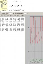
We can look at a PSUD2 session to analyse the current.
The dc current of 4A translates into an rms current of about 8A in the secondary winding - hence the recommendation to use 9V 12A: it is best not to run a trafo at 100% full load for hours of listening time!
Best buy for UK DIYers is the JMS 150VA trafo, configured with 9V secondary, 240V primary:
150 VA
This should run quite cool.
The rms current in each diode is about 5.7A, so heatsinking may well be needed at this high level, or you could try MBR1645 for lower drop. Beware that the TO220 package tabs are not isolated -please use a Mica insulator and grease.
I am pleased that you like the sound!
Attachments
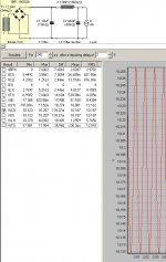
A much better supply can be made with a choke-input arrangement.
The transformer is 12V 6A trafo (eg Hammond 266M24) and a 10mH 5A choke e.g. Hammond 159ZJ.
The rectifier diode current drops below 3A, and the pulse-current drawn from the supply are much lower, meaning less chance of EM-coupling to other wires or trafos.
The transformer is 12V 6A trafo (eg Hammond 266M24) and a 10mH 5A choke e.g. Hammond 159ZJ.
The rectifier diode current drops below 3A, and the pulse-current drawn from the supply are much lower, meaning less chance of EM-coupling to other wires or trafos.
Attachments
Hi Rod,
I'm considering how to update my TRAM with your regs. I use 2A3s. I could do choke input similar to the above if I use a 2nd chassis attached under the TRAM. heatsinking will then be easy to organise. The trafo and diodes will need to be different. Have you spec'ed anything similar previously?
Cheers,
Clive
- Home
- Amplifiers
- Tubes / Valves
- New DHT heater