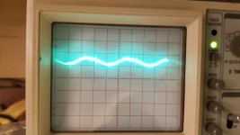
I'm (in theory) almost done with my 6L6GC amp build, and for the most part the performance is excellent. I had the chance to measure it with an Audio Precision, and the THD was around .2% (often much lower) from 20 hz to 20Khz. That said, the noise floor was around -40 dB. My oscilloscope read about 20mV of noise on the outputs. I have spent many, many hours trying to find the problem. Things I have tried:
-Powering the heaters off of of 6V batteries
-Clipping in a pair of 2900 uF @250V capacitors (Series for 500V) in parallel with the first filter capacitor bank (Also tried putting them in parallel with the second filter capacitors)
-Additional filtering at the phase inverter rail
-Additional filtering at the 200V rail for the 12AX7
-Switched 12AX7s
-Moved Bridge Rectifier a little
-Disconnected the feedback loop for these tests to avoid false readings
-Rotated toroidal transformer at great pain (6L6s are HOT)
-Put a tube shield over 12AX7
-Ran bias off of a regulated HV power supply
-Increased the size of the B+ filtering resistor
-Other things I'm forgetting I did.
Other notes:
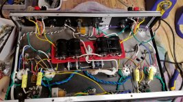
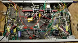
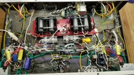
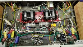
-I know this is NOT the cleanest or best planned layout / point-to-point wiring job in history. I am not necessarily proud of what the inside looks like, and it WILL be tidied up once I get everything working right.
-Wires running from the input jack to the 12AX7 are sheilded, as are the wires running from the 12AX7 plates to the 6SN7 grids.
-Not all these pics were taken at once- I ended up removing the power supply and PT in its entirety, and I've been experimenting with orientation of the filter capacitor banks. Likewise, these oscilloscope images were taken with the PS in its original orientation.
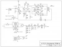
-The attached schematic pics are drawn as the amp is built, hence some of the series resistor values.
-Odd capacitor choices were simply due to what was on hand. This amp ended up costing only about $350, as the only things I bought were 6SN7s, output transformers and a power transformer. Everything else was what I had on hand.
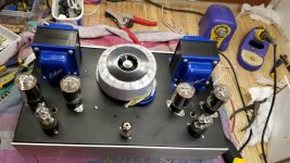
-This is a fairly small chassis. It is a wide (rackmount) chassis, however it is not very deep.
-I will post some more oscilloscope images and information tomorrow when I have a chance to take pictures of my measurements. Unfortunately channel 2 on my scope crapped out yesterday.I can't show both channels at once from here on out. Sorry about that.
-I'm seeing an awful lot of noise on the plate of the 12AX7, without feedback connected, which leads me to believe that this stage is probably somehow causing the problem.
-The +200V supply for the 12AX7 is dead quiet. Much quieter than the plate. I shorted the grid of the 12AX7 to ground, and it may have been slightly better (this can be hard to tell at times...), but no matter what it's hard to measure because my scope has a minimum of 5mv per division, so a .1 mV signal on the input (which would get amplified by a factor of 30 and be significant on the output) is really hard to even know about.
There is only a volt or two of ripple on the supply for the power tubes, and a bit less for the phase inverter. Reducing this ripple seemed to have a minimal impact.
I'm open to design modifications, even big ones. I'd prefer not to do any drastic chassis work at this point if I can avoid it, however.
My personal theory is that the preamplifier stage is causing a lot of the noise due to 1) the high gain of the 12AX7 and 2) it seems to be poorly located.
The 12 gauge solid copper wire that is the main ground is about 2.5" from the chassis- too far methinks. Perhaps having some of the components this far from the shielding of the chassis is part of the problem? I'd love some input on this as well as my grounding scheme from some of those with more experience than me.
At this point, I'm running out of things to try to fix the problem.
This is my first tube power amp build, so I'm a little new to this. In the interest of making this post a little more useful, Here are a few things that I can suggest if you're about to start your first build:
-Don't try to squeeze it all into an undersized chassis.
-Plan ALL of the details ahead of time
-Don't put the bias/balance pots in between the power tubes thinking it will stop them from getting bumped by accident. All this leads to is burned fingers.
-Plan out and install lots of terminal strips.
-Don't be a cheapskate and try to use unsuitable parts just because you have them (e.g. 4 caps in series for the main filter... takes up half the chassis)
Sorry to bug you all with a rather specific thread like this, I'm hoping it will end up being useful to others as well.
My oscilloscope read about 20mV of noise on the outputs. I have spent many, many hours trying to find the problem. Things I have tried:-Powering the heaters off of of 6V batteries
-Clipping in a pair of 2900 uF @250V capacitors (Series for 500V) in parallel with the first filter capacitor bank (Also tried putting them in parallel with the second filter capacitors)
-Additional filtering at the phase inverter rail
-Additional filtering at the 200V rail for the 12AX7
-Switched 12AX7s
-Moved Bridge Rectifier a little
-Disconnected the feedback loop for these tests to avoid false readings
-Rotated toroidal transformer at great pain (6L6s are HOT)
-Put a tube shield over 12AX7
-Ran bias off of a regulated HV power supply
-Increased the size of the B+ filtering resistor
-Other things I'm forgetting I did.
Other notes:
-I know this is NOT the cleanest or best planned layout / point-to-point wiring job in history. I am not necessarily proud of what the inside looks like, and it WILL be tidied up once I get everything working right.
-Wires running from the input jack to the 12AX7 are sheilded, as are the wires running from the 12AX7 plates to the 6SN7 grids.
-Not all these pics were taken at once- I ended up removing the power supply and PT in its entirety, and I've been experimenting with orientation of the filter capacitor banks. Likewise, these oscilloscope images were taken with the PS in its original orientation.
-The attached schematic pics are drawn as the amp is built, hence some of the series resistor values.
-Odd capacitor choices were simply due to what was on hand. This amp ended up costing only about $350, as the only things I bought were 6SN7s, output transformers and a power transformer. Everything else was what I had on hand.
-This is a fairly small chassis. It is a wide (rackmount) chassis, however it is not very deep.
-I will post some more oscilloscope images and information tomorrow when I have a chance to take pictures of my measurements. Unfortunately channel 2 on my scope crapped out yesterday.
I can't show both channels at once from here on out. Sorry about that.-I'm seeing an awful lot of noise on the plate of the 12AX7, without feedback connected, which leads me to believe that this stage is probably somehow causing the problem.
-The +200V supply for the 12AX7 is dead quiet. Much quieter than the plate. I shorted the grid of the 12AX7 to ground, and it may have been slightly better (this can be hard to tell at times...), but no matter what it's hard to measure because my scope has a minimum of 5mv per division, so a .1 mV signal on the input (which would get amplified by a factor of 30 and be significant on the output) is really hard to even know about.
There is only a volt or two of ripple on the supply for the power tubes, and a bit less for the phase inverter. Reducing this ripple seemed to have a minimal impact.
I'm open to design modifications, even big ones. I'd prefer not to do any drastic chassis work at this point if I can avoid it, however.
My personal theory is that the preamplifier stage is causing a lot of the noise due to 1) the high gain of the 12AX7 and 2) it seems to be poorly located.
The 12 gauge solid copper wire that is the main ground is about 2.5" from the chassis- too far methinks. Perhaps having some of the components this far from the shielding of the chassis is part of the problem? I'd love some input on this as well as my grounding scheme from some of those with more experience than me.
At this point, I'm running out of things to try to fix the problem.
This is my first tube power amp build, so I'm a little new to this. In the interest of making this post a little more useful, Here are a few things that I can suggest if you're about to start your first build:
-Don't try to squeeze it all into an undersized chassis.
-Plan ALL of the details ahead of time
-Don't put the bias/balance pots in between the power tubes thinking it will stop them from getting bumped by accident. All this leads to is burned fingers.
-Plan out and install lots of terminal strips.
-Don't be a cheapskate and try to use unsuitable parts just because you have them (e.g. 4 caps in series for the main filter... takes up half the chassis)
Sorry to bug you all with a rather specific thread like this, I'm hoping it will end up being useful to others as well.
Attachments
-
 12AX7 Plates.jpg889.5 KB · Views: 642
 -
 Output.jpg913.9 KB · Views: 598
 -
 Ch A.jpg724.8 KB · Views: 602
 -
 Ch B.jpg772.9 KB · Views: 589
 -
 Half Finished.jpg973.1 KB · Views: 592
 -
 Inside.jpg932.3 KB · Views: 297
 -
 Preamp Stage.jpg999.1 KB · Views: 281
 -
 Top Layout.jpg667.3 KB · Views: 320
 -
Butchered Amp Schematic.bmp96.3 KB · Views: 180
Last edited:
OK, I'll start the ball rolling...…
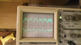
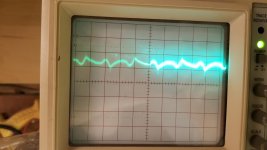
Many of the same rules apply to both solid state and valve and I think its fair to say the issues here are more than likely down to the implementation. The scope traces show what look to be PSU related charging pulses making their way into the audio circuitry.
That long grounding buss bar. Is it electrically connected to the chassis at both ends or at more than one point ? If so then that could allow chassis induced currents to circulate.
Also, if that buss bar caries any PSU charging pulses (such as reservoir or rail decoupling cap returns) then those currents will in turn develop small volt drops along the buss bar and that in turn means any more critical points of the circuit returned to that bar will see those voltages as 'valid' signals and amplify them.
Things like that would be the first things to look at.
All the audio ground related points such as the input socket ground, R2, R5, R11, R12, C2 and so on must be taken to a clean point that serves as an absolute reference point. That point must not be influenced by currents from any of the decoupling and reservoir caps.
While attempting to troubleshoot this you should also have shorting plugs fitted to the inputs. Don't leave them floating.
Power supply caps in series should each have a bleed/balancing resistor.
Look up basic rectifier grounding scheme - your bridge neg goes to middle of busbar, rather that first cap neg terminal, and bridge pos should go to first cap pos terminal - directly (do not pass go and do not collect $200).
Using local star grounding (ie. remove the busbar) forces you to work out which parts form a local circuit stage. Some old valve schematics show that functional local star grounding and B+ distribution scheme.
Have you looked at this article, which is highly recommended:
The Valve Wizard
With a ground busbar approach, it is vital to connect things to the bus in the right order: in the same order as the signal path, with each power supply cap connected at the position where that cap feeds the corresponding signal stage. In particular, the ground from the bridge-rectifier must have a dedicated connection to the ground of the reservoir cap (i.e. nothing else should be connected to the link between those two points).
Last edited:
The circuit diagram in post 1 seems to be something else. Check you have posted the correct file.
Poor grounding is almost certainly the problem.
A bus ground can work fine, but you have to be careful about the order you attach things. In particular, the PSU charging loop must never incorporate the ground bus; instead, just connect the negative of the final PSU cap to the bus. The negative of the first PSU cap must connect straight to the secondary/rectifier arrangements.
I had a Knight KG400. It caused objectionable hum at first phono tube. Schematic did spec a 7025 low noise twisted filament tube in first phono section. Removing the 12AX7 and replacing a 7025 lowered hum some, but still objectionable. I installed an IC regulated power supply to the 1st phono tube filament. About -80dB down for hum. Surprised at no difference in hum after installing the IC.
I check all wiring and it looked good using shielded wire. I could not find anything wrong. Even the input jacks were electrically isolated from the chassis and a ground wire brought back to a central grounding point. I just laid blame on the amplifier layout.
I check all wiring and it looked good using shielded wire. I could not find anything wrong. Even the input jacks were electrically isolated from the chassis and a ground wire brought back to a central grounding point. I just laid blame on the amplifier layout.
Have you looked at this article, which is highly recommended:
The Valve Wizard
With a ground busbar approach, it is vital to connect things to the bus in the right order: in the same order as the signal path, with each power supply cap connected at the position where that cap feeds the corresponding signal stage. In particular, the ground from the bridge-rectifier must have a dedicated connection to the ground of the reservoir cap (i.e. nothing else should be connected to the link between those two points).
Thanks, this is exactly the kind of thing I've been looking for.
I had a Knight KG400. It caused objectionable hum at first phono tube. Schematic did spec a 7025 low noise twisted filament tube in first phono section. Removing the 12AX7 and replacing a 7025 lowered hum some, but still objectionable. I installed an IC regulated power supply to the 1st phono tube filament. About -80dB down for hum. Surprised at no difference in hum after installing the IC.
I check all wiring and it looked good using shielded wire. I could not find anything wrong. Even the input jacks were electrically isolated from the chassis and a ground wire brought back to a central grounding point. I just laid blame on the amplifier layout.
I know my layout is sub-optimal, I have a 120V to 120V transformer for the bias supply about 1" from an input jack... Not a whole lot I can do about it though. I made some design compromises to keep a perfectly clean front panel, and in hindsight I probably would have been wise to 1) use a smaller (less overkill) PT, and 2) probably lay out the filtering in a better way.
Out of curiosity, aside from wasting a lot of chassis space, are there any downsides to using four capacitors in series like this? I know I should have voltage equalizing resistors on them, but is there a formula for calculating the proper value of them?
The value of equalising resistors should be such that they draw a current of several magnitudes more than the leakage current of the cap. So check the data sheets for that cap (or similar) to get an idea of the current. Take the total supply voltage and divide it by 4 to get the voltage across each cap and then calculate the resistance needed (R=V/I) and add that calculated value (nearest standard value) across each cap.
if your amp is not direct coupled between stages you can remove the 12AX7 and see if the hum disappears.
This will remove the gain ( 1st) stage and then pass any B+ noise forward.
hum is at a good level if you cannot hear it with your ear next to the woofer.
if it is being amplified, shorting the input to ground should reduce the noise.
if the bare copper wire is ground, you can connect it to the chassis at several points to eliminate ground loops there.
your large primary filter caps' Ground (-) should connect directly to the transformer center tap then from there to chassis.
if not center tapped, then the rectifier outputs both go to the resevoir caps and the ground ( - ) goes from the caps to the ground line.
if AC current passes through the ground wire, it will be amplified.
Last edited:
Okay here is where things stand.
I made some improvements to the grounding scheme (I think) and cleaned up the mess (Though I'm not 100% sure that zip-tying all the ground wires together (and a few signal ones...) is a good idea. Noise floor is measured at -45dB.
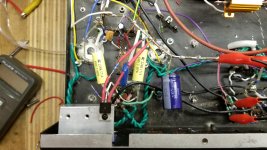
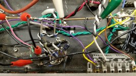
Fig 1 shows the grounding scheme, and I've circled various points (color coded) to make it easier to see where things go.
Pink: Filament virtual center tap
Red: Bias supply and second B+ filter capacitor ground.
Blue: 6L6 cathode resistor (R19 and R20) ground
Yellow: 12AX7 ground points (R5 and R2)
Light turquois: Input jack grounding
White: Capacitor for 400V supply
Black: Capacitor for 200V supply
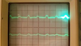
The oscilloscope images show the outputs. Fig 2 shows the channel in the right side of the chassis diagram, while Fig 3 shows the left.
The plates of the 12AX7 show a smaller version of the same signal, so I feel like this is still the source of my problems.
In order to ground certain points (like the 6L6 Cathode resistors) to the correct area, I wound up having to use longer lengths of wire than I would have liked, so I'm wondering if that has anything to do with this.
Otherwise, I could rip out the whole bus grounding scheme and try to go with a star ground scheme, with one star for the PSU, one for the 12AX7, and one for each Phase inverter and power tube channel. That's sort of what I tried to do, but I'm not sure I executed it as well as I should have.
And yes, the inputs are shorted. Not to worry.
Any suggestions on how I should go about this is greatly appreciated. I've spent enough time trying to correct this that if all I had to do was create one great big star in the middle, run wires from every component to said star and rip out all the bus-grounding, I would have no problem taking the time to do it.
I made some improvements to the grounding scheme (I think) and cleaned up the mess (Though I'm not 100% sure that zip-tying all the ground wires together (and a few signal ones...) is a good idea. Noise floor is measured at -45dB.
Fig 1 shows the grounding scheme, and I've circled various points (color coded) to make it easier to see where things go.
Pink: Filament virtual center tap
Red: Bias supply and second B+ filter capacitor ground.
Blue: 6L6 cathode resistor (R19 and R20) ground
Yellow: 12AX7 ground points (R5 and R2)
Light turquois: Input jack grounding
White: Capacitor for 400V supply
Black: Capacitor for 200V supply
The oscilloscope images show the outputs. Fig 2 shows the channel in the right side of the chassis diagram, while Fig 3 shows the left.
The plates of the 12AX7 show a smaller version of the same signal, so I feel like this is still the source of my problems.
In order to ground certain points (like the 6L6 Cathode resistors) to the correct area, I wound up having to use longer lengths of wire than I would have liked, so I'm wondering if that has anything to do with this.
Otherwise, I could rip out the whole bus grounding scheme and try to go with a star ground scheme, with one star for the PSU, one for the 12AX7, and one for each Phase inverter and power tube channel. That's sort of what I tried to do, but I'm not sure I executed it as well as I should have.
And yes, the inputs are shorted. Not to worry.
Any suggestions on how I should go about this is greatly appreciated. I've spent enough time trying to correct this that if all I had to do was create one great big star in the middle, run wires from every component to said star and rip out all the bus-grounding, I would have no problem taking the time to do it.
Attachments
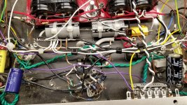
Ok, one simple question: where on the picture does the ground buss 'connect' to chassis ground?
Did you try connecting the chassis earth (top right of picture) directly to different points along the buss and seeing if it makes any difference?
You know you will eventually have to re-do the whole ground scheme as everyone is telling you...
Did you try connecting the chassis earth (top right of picture) directly to different points along the buss and seeing if it makes any difference?
You know you will eventually have to re-do the whole ground scheme as everyone is telling you...
Won't this create extra ground loops? A ground bus may have one and only one chassis connection.stocktrader200 said:if the bare copper wire is ground, you can connect it to the chassis at several points to eliminate ground loops there.
It isn't a good idea, as it encourages coupling.H713 said:Though I'm not 100% sure that zip-tying all the ground wires together (and a few signal ones...) is a good idea.
Changing from a bus to a star might help, or might make no difference at all. It all depends on where your grounding mistakes are. Be aware that a star is actually a short bus, but one where you will probably have given up all attempts to get the connection order right. People often get a star wrong: two common mistakes are mounting the star actually on the chassis, and including the star in the PSU charging loop.
The photos don't help us as much as you might expect. I still have not seen a circuit diagram. Debugging someone else's rats nest remotely is not easy, especially when most of the wires seem to be black or white.
Let's start with some basics. Where is the twisted pair carrying the high voltage secondary to the rectifiers? Where is the twisted pair from the rectifiers to the reservoir caps? Exactly how is the cap negative grounded? Can you assure us that this circuit loop has no other ground point?
Here is the circuit as posted in #1.
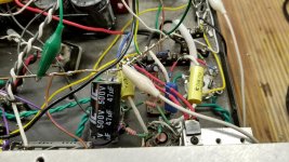
The pictures are not easy, but there is a simple error round the bias pots (R21?). The yellow wires share the input ground, they should go to the red circle point. Also C5 and C6 should return their +ves to the red circle.
The Input Jack Ground, is in my opinion wrong. I would join it to the white wire from the 1 meg resistors. (That would be my first try at the link to chassis ground too.) Then the yellow circle is joined to the buss at the wrong end. And so on.
Others will have other ideas and contradictions, and what works for amp A does not work so well for amp B. All part of the interest and frustration...
Please refer to the Valve Wizard info the Malcolm lists in his post #6 http://www.valvewizard.co.uk/Grounding.pdf it has everything you need. Figure 15.10b and 15.13 are good references.
Alan
Attachments
- Status
- This old topic is closed. If you want to reopen this topic, contact a moderator using the "Report Post" button.
- Home
- Amplifiers
- Tubes / Valves
- Eliminating Hum and Noise from Amp