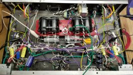
the large blue cap may be a problem as it looks to be connected from the bare wire to chassis. there should be no dc across this connection but it may form a ground loop.
is your buzz 60hz or 120hz?
60hz is likely magnetic induction pickup
120Hz is a rectification / ground loop problem
is your buzz 60hz or 120hz?
60hz is likely magnetic induction pickup
120Hz is a rectification / ground loop problem
Last edited:
the large blue cap may be a problem as it looks to be connected from the bare wire to chassis. there should be no dc across this connection but it may form a ground loop.
Nope, there's a terminal strip that you can't see in the pics. BTW, it is an aluminum chassis.
The bus is only connected to the chassis in one place, at the end of the bar on the right side. It is connected with a 1K resistor and a brown wire.
Is there any reason I would want to switch the order of the filter caps, putting the larger bank second? It's easy to change, but I've heard some conflicting opinions on this...
Changing the caps around should decrease the charging pulse peaks from the power transformer also I would want the most uF's after the resistor to be able to supply the most current to the tubes with the least resistance when they ask for it. ie. decrease power supply sag.
If you are having magnetic induction try placing something steel between the power transformer and output transformer. Move it in and out and watch the scope.
If you are having magnetic induction try placing something steel between the power transformer and output transformer. Move it in and out and watch the scope.
Alright, I haven't had much time to work on the amp today. I expected to get a lot done, but we got 10 inches of rain  (in just a few hours) in my part of the state, and I spent several hours today pulling pier sections out at the park and doing other related stuff. The lake level has risen 18 inches already (so it's about 2.5 feet over the summer maximum) and it's expected to rise at least another ten inches from the runoff. And there's more rain in the forecast...
If any of you are in southern Wisconsin, I hope you're all staying dry.
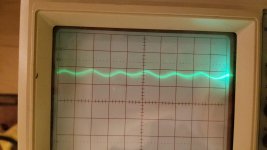
That aside, I fixed the grounds for the bias circuit (minimal impact), and switched around the capacitors. That made a big difference, bringing the hum down to -56dB. Attached are some oscilloscope images.
The scope was set to 5ms per division and 10 mV per division.
But that suggests that I've got something like 150 Hz hum.
Either way, I'm starting to wonder if that's power supply ripple. I would think I've got enough filtering, but I'm not sure. It doesn't have the same defined charging pulses that it had before. I did replace the two 100 uF capacitors with a pair of 220 uF capacitors, so I have about 110 uF there instead of 50.
The other big improvement is that both channels match, whereas before they did not.
(in just a few hours) in my part of the state, and I spent several hours today pulling pier sections out at the park and doing other related stuff. The lake level has risen 18 inches already (so it's about 2.5 feet over the summer maximum) and it's expected to rise at least another ten inches from the runoff. And there's more rain in the forecast...If any of you are in southern Wisconsin, I hope you're all staying dry.
That aside, I fixed the grounds for the bias circuit (minimal impact), and switched around the capacitors. That made a big difference, bringing the hum down to -56dB. Attached are some oscilloscope images.
The scope was set to 5ms per division and 10 mV per division.
But that suggests that I've got something like 150 Hz hum.
Either way, I'm starting to wonder if that's power supply ripple. I would think I've got enough filtering, but I'm not sure. It doesn't have the same defined charging pulses that it had before. I did replace the two 100 uF capacitors with a pair of 220 uF capacitors, so I have about 110 uF there instead of 50.
The other big improvement is that both channels match, whereas before they did not.
Attachments
There is more to low PSU ripple than filtering. As we keep saying, grounding matters too. You can have humungously large caps and still have bad ripple if the charging loop gets connected to the circuit ground in the wrong way.H713 said:Either way, I'm starting to wonder if that's power supply ripple. I would think I've got enough filtering, but I'm not sure.
There is more to low PSU ripple than filtering. As we keep saying, grounding matters too. You can have humungously large caps and still have bad ripple if the charging loop gets connected to the circuit ground in the wrong way.
I think that the filter caps are grounded properly now. They certainly weren't before- but the negative side of the bridge rectifier connects directly to the first filter cap, which is then grounded to the power supply bus. I know it's a little hard to see (as you mentioned I did use a lot of black and white wires), but none of the sensitive circuitry is in the charging loop, and the inputs are grounded by the grounds for the input stage. I'm happy to take suggestions on what should be changed in the current setup.
The only thing I can think of that is a potential problem with the grounding scheme as of right now is that some of the wires tying various components to ground are rather long.
I suspect it's 120 Hz hum (140 Hz would seem odd), which would suggest it isn't from bad heater wiring.
- Status
- This old topic is closed. If you want to reopen this topic, contact a moderator using the "Report Post" button.
- Home
- Amplifiers
- Tubes / Valves
- Eliminating Hum and Noise from Amp