About the C4S regulation, in this site I found the reference:
T-Project 1: Preamplificatore a Valvole "Meeting"
T-Project 1: Preamplificatore a Valvole "Meeting"
I always feel that way about circuits like this. If you end up using more transistors than tubes, to 'fix' all the shortcomings of the tubes by strong-arming them with CCS's everywhere, why the heck are you using tubes at all??You can build a better amp using just the 3 transistors and use the tubes for decoration only.


I always feel that way about circuits like this. If you end up using more transistors than tubes, to 'fix' all the shortcomings of the tubes
I look at it the opposite way. There's a theoretical vacuum tube Eden where you can get all the gain the tube has to offer and minimal distortion, and all that's required are a few BJTs, diodes, and resistors. Another way to look at it is that one could just use a very high voltage supply and very high value plate load resistors to achieve the same results.
But, sure, you could use a couple of opamps and 60dB of feedback and proclaim yourself the king (you all know who I'm talking about), but then you'd be in the wrong forum and not really providing any help to the OP.
There's a theoretical vacuum tube Eden....
You can't get theah, from heeah.... The theoretical one, that is. The pursuit of perfection is never satisfied.
I always feel that way about circuits like this. If you end up using more transistors than tubes, to 'fix' all the shortcomings of the tubes by strong-arming them with CCS's everywhere, why the heck are you using tubes at all??
Because it is much easier to fix shortcomings of tubes than get similar results with transistors only.
This guy seems to have a nice little three transistor power amp going..Because it is much easier to fix shortcomings of tubes than get similar results with transistors only.
https://www.eeweb.com/extreme-circuits/30-watt-audio-power-amplifier
I didn't examine too deep, but performance looks to be up to par with very good tube amps, and the dreaded x-over distortion is much alleviated by the mosfet outputs.
This guy seems to have a nice little three transistor power amp going..
https://www.eeweb.com/extreme-circuits/30-watt-audio-power-amplifier
I didn't examine too deep, but performance looks to be up to par with very good tube amps, and the dreaded x-over distortion is much alleviated by the mosfet outputs.
Neat.
I used to build a bunch of similar circuits when I first got into electronics. Replace that first transistor with a 6111WA tube and you have something similar to what I used as my main amplifier for nearly ten years.
Think about SiC Schottky diodes. The cleanest I've heard to date. Check out the post below.
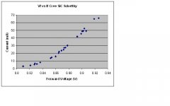
Vf vs If for Cree Sic Schottky Diode - Measured at cathode-relevant Currents - Maxamillion - Tube DIY Asylum
String of CSD01060A with forward voltage 1.6 - 1.8V and price 1.17 Euro from Farnell seems to be a good fit. However, look at the graph attached from manufacturer's data sheet. At low currents (typical for vacuum tube circuits) forward voltage drop is only 0.8V and have non-linear region which have to be determined with test.
Anyone actually have tried Schottky diodes in cathode bias?
Theory is one thing yet real life could be very different.
Attachments
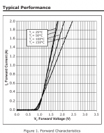
String of CSD01060A with forward voltage 1.6 - 1.8V and price 1.17 Euro from Farnell seems to be a good fit. However, look at the graph attached from manufacturer's data sheet. At low currents (typical for vacuum tube circuits) forward voltage drop is only 0.8V and have non-linear region which have to be determined with test.
Anyone actually have tried Schottky diodes in cathode bias?
Theory is one thing yet real life could be very different.
Yes, I use them for biasing the 6e5P driver tubes in my 833C amps. They work great. Sound is very clean and clear. I also used them in a preamp with the same results.
I've attached an If vs Vf curve which I measured myself, very linear in the range of currents I'm using (25-35mA) with a very low dynamic resistance.
Amp build thread with schematics also linked below.
The Midlife Crisis - My 833C Amp Build
Attachments
Last edited:
I always feel that way about circuits like this. If you end up using more transistors than tubes, to 'fix' all the shortcomings of the tubes by strong-arming them with CCS's everywhere, why the heck are you using tubes at all??
Merlin,
You are 100% correct.
Sometimes I am a bit ambivalent. If the tube pre-amp is part of an instrument amplifier, if it sounds like a Marshall that is a good thing. Put the same pre-amplifier inside a “Hi-Fi” and we may be changing things up a bit.
Thinking “HI-Fi” I am all about the tubes until I start in on the power supply and the mains frequency / harmonics. Run an FFT with the amplifier idling with no signal you will see the mains frequency / harmonics sticking up above the noise floor. Turn on a 1000Hz test signal and you will see a 1K fundamental plus a series of harmonics. You will also see the ugly part, a whole series of intermodulation distortion spawned from the mains frequency / harmonics and the test signal. This is not just noise; it persists even with averaging samples and increasing sample size.
Regulated SS power supplies can be a good thing in tube amplifiers. Blur the line between power supply and amplifier and soon every tube has its’ own CCS, yuck.
DT
I look at it the opposite way. There's a theoretical vacuum tube Eden where you can get all the gain the tube has to offer and minimal distortion, and all that's required are a few BJTs, diodes, and resistors. Another way to look at it is that one could just use a very high voltage supply and very high value plate load resistors to achieve the same results.
I would say that I view this as a truly viable path for design as well. I have started to diagram out a few ideas for myself but nothing I've planed to build yet. Maybe it's time I tried. I'm planning on doing a build where I see how far I can push my skill doing this but I am curious if you have any example circuits that truly exemplify this.
- Status
- This old topic is closed. If you want to reopen this topic, contact a moderator using the "Report Post" button.
- Home
- Amplifiers
- Tubes / Valves
- LED choice in cathode biasing