The 1Nx types are noisy. Also, the forward voltage varies quite a bit with temperature..
When they are switching, yes. Conducting in a DC environment, not so much. Or not enough ot loose any sleep over.
TEmperature drift is easliy controlled too
How do you control 2mV/˚C? With a typical forward voltage of .7V and assumed operating range 10-40˚C, temp drift can be quite a bit!TEmperature drift is easliy controlled too
For one thing, you can achieve the same with much less parts.What do you think about this?
I mean to improve the Bottlehead, I wonder if can be the way for approaching the "speedball" (I don't have it)
If one does not have something on which they intend to improve, how would they verify the effects of their efforts?
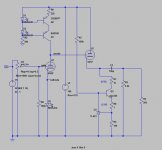
You can throw out a few resistors and also reduce energy consumption a bit as you go. What's the supposed operating point of the 6AS7? Maybe I will sketch it up for you.
It should operate with Vc= -25/30 V and Ia = 35-40 mA. You can also send me MP, thanks a lot
How do you control 2mV/˚C? With a typical forward voltage of .7V and assumed operating range 10-40˚C, temp drift can be quite a bit!
10 degrees? What are you operating in, a chiller?
realistically, 20-40 degrees, 2mV/degree is 0.04V shift maximum, or around 6%. A resistor is going to be around that anyway, let alone the specs on the tube itself.
Additionally, once AT its operating temp, there would be minimal drift - it may range around 25% of what we are discussing (35 - 40 degrees) so the drift becomes insignificant.
The 1Nx types are noisy. Also, the forward voltage varies quite a bit with temperature..
Well, yes … as do all diodes including LEDs. They all follow essentially the same exact response formula, don't they?
I = IS (( e(VD / nVT) - 1) where
VT = kT/q;
The only thing that changes is the 'n' and the IS reverse bias saturation current. Which of course is different for each PN junction material bandgap and so on.
You may do better with non 1Nxx diodes, but essentially the same parameter(s) are at play. The usual method of quenching most of that noise is to insert a 47 Ω resistor in series with the stack, and a 4700 μF smoothing/bypass capacitor around it the thing. But purists will balk at using capacitors.
If temperature compensation is what's desired, then I personally would abandon the LED (or diode-chain) technique, and just buy-or-build a small, well regulated, negative voltage supply to bias the grid where you want it to be. Since it supplies next-to-no current, filtering is easy.
Anyway… I've got to get back to construction. With nails and putty. That kind.
GoatGuy
I mean to improve the Bottlehead, I wonder if can be the way for approaching the "speedball" (I don't have it)
plug your headphones in the computer output jack...
- apple output are very bad no matter which computer/ipod/phone
- pc gaming motherboard's some have very good chips. /tried julii and audiophile"" cards, mod them, minor improvement not even worth the trouble.
I guess that is a sad dose of reality.
Ok, I simmed it in spice but still don't get it. It is not a well balanced circuit in any way.What do you think about this?
Whats's the purpose of R1?
Whats's the purpose of R8?
You can build a better amp using just the 3 transistors and use the tubes for decoration only.
- Status
- This old topic is closed. If you want to reopen this topic, contact a moderator using the "Report Post" button.
- Home
- Amplifiers
- Tubes / Valves
- LED choice in cathode biasing