
Testing the input, connected the Oscilloscope to the input Attenuator Output

The noise voltage is about 36mV
Testing the first stage 310A

Noise voltage is about 31mV
Testing the second stage 310A

Noise voltage is about 4.4V (seems main noise coming from this stage)
Testing the output

Noise voltage is about 125mV
The noise voltage is about 36mV
Testing the first stage 310A
Noise voltage is about 31mV
Testing the second stage 310A
Noise voltage is about 4.4V (seems main noise coming from this stage)
Testing the output
Noise voltage is about 125mV
Unplug V1 and V2,Like troubleshooting any amplifier, start from the output and work your way towards the 1st stage. So unplug V1 and V2, is there still hum? If so, then you got problem with V3. If not, plug in V2, and repeat...

hum reduced a lot, but still have some, about 40mV

I think B+ fluctuation is too much, which affected the AMP circuit, is it possible?
review the PSU I found 2 problems
this is the circuit of PSU

problem 1#
the res and cap of 300B cathode (in the red circle), it is not right to put them in PSU-PCB, should put them into AMP-PCB
it provides FB to the grid of 300B, it is wrong to put them in PSU-PCB, it will bring noise of PSU back to the grid of 300B

problem 2#
the Decoupling circuit of 310A (green circle is of 1#310A, blue circle is of 2#310A), should I put them into AMP-PCB? or it is OK to leave them in the PSU-PCB?
this is the circuit of PSU
problem 1#
the res and cap of 300B cathode (in the red circle), it is not right to put them in PSU-PCB, should put them into AMP-PCB
it provides FB to the grid of 300B, it is wrong to put them in PSU-PCB, it will bring noise of PSU back to the grid of 300B
problem 2#
the Decoupling circuit of 310A (green circle is of 1#310A, blue circle is of 2#310A), should I put them into AMP-PCB? or it is OK to leave them in the PSU-PCB?
Hi Jerry!
Nice project and good work so far, congratulation!")
I guess your hum issue (40mV) is caused by the AC filament supply. You should at least spend a hum balance pot to reduce it as far as possible. I think B+ fluctuation isn't that critical here (300B).
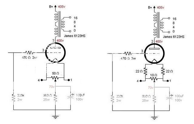
But with your 97dB speaker this won't be enough so you should think about DC Filament supply. Even better is a modern module like Tentlabs or Rod Colemans solution but this wouldn't fit well into your 1:1 concept.
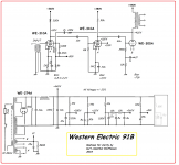
I also think it's hard to work with the original WE schematic layout. Kurt Lilienthal did a great job with redrawing it:
Nice project and good work so far, congratulation!
I guess your hum issue (40mV) is caused by the AC filament supply. You should at least spend a hum balance pot to reduce it as far as possible. I think B+ fluctuation isn't that critical here (300B).
But with your 97dB speaker this won't be enough so you should think about DC Filament supply. Even better is a modern module like Tentlabs or Rod Colemans solution but this wouldn't fit well into your 1:1 concept.
I also think it's hard to work with the original WE schematic layout. Kurt Lilienthal did a great job with redrawing it:
Attachments
Hi Troy, thank you for your help
1, My power trans has center-tap for 300B heater, if I used hum balance pot, the center-tap will no longer used, will it affect the FB from cathode to grid of 300B?

2, if I change the heater of 300B from AC to DC, then connected DC in this way, is it?

3, Kurt's redrawing is the most closet schematic to original WE-91B, but some res and cap is different from original one

will this change affect the final sound?
I redesigned the circuit of PUS and AMP

I set 5 GND points in AMP, because it is flexible to change the grounding method in the final assemble.
I will try this two method of grounding to see which one will have the minimum hum

The PSU PCB design


GND wiring

Finished PSU wiring, quite easy

The AMP-PCB, res and cap grouped in 3 sections(V1 V2 and V3) according their relation with the tube

1, My power trans has center-tap for 300B heater, if I used hum balance pot, the center-tap will no longer used, will it affect the FB from cathode to grid of 300B?
2, if I change the heater of 300B from AC to DC, then connected DC in this way, is it?
3, Kurt's redrawing is the most closet schematic to original WE-91B, but some res and cap is different from original one
will this change affect the final sound?
I redesigned the circuit of PUS and AMP
I set 5 GND points in AMP, because it is flexible to change the grounding method in the final assemble.
I will try this two method of grounding to see which one will have the minimum hum
The PSU PCB design
GND wiring
Finished PSU wiring, quite easy
The AMP-PCB, res and cap grouped in 3 sections(V1 V2 and V3) according their relation with the tube
Hi Jerry,
1. Yep, that's correct.
2. Yes, you can also use the balance pot for DC to eliminate the ripple which is still left. If you use the 5V tap and a simple bridge rectifier you should use a modest size high quality cap because it's part of you signal path.
3. Parallel components are considered as single components, just as Western Electric would have used if they had access to modern components. These four 20uF caps (C10..C13) can be replaced with one 20uF/500V and C8/C9 can be replaced with one 10uF/500V.
C1 can be 20uF or more...
I would prefer your GND - Plan 2#
Did you already measure the frequency response?
Have a look at the attached document. The original 91A/B is tuned to a peak at 7kHz and also limited at 15 kHz because of the Miller capacity (310A) and the output transformer (171A).
You could also have a look at the original wiring/cabling.
Later on you can tune the feedback frequency peak from 7 kHz to 20 kHz (or higher) to get an extended and flat response.
You should also think about shielding the two 310A tubes. Put your finger on (or just close to) the ceramic grid-cap and you see/hear how sensitive they are...
Attachments


There are mainly 3 types of hums:
1) AC leaks through heat filament
2) Hum due to insufficient AC filtering
3) Ground loop
Do you have an input transformer? If so, the ground loop should be already broken, but due high sensitivity a little hum due to 1) and 2) can be amplified a lot. For 1) and 2) you can build a switch to momentary switch off the AC supply of the respective circuit to see if hums would drop. AC hums is quite distinguishable from psu hum as they are 50/60Hz where the psu hum freq is doubled. You can also try another tubes esp the front 2, some tubes have more leakage in filaments and required more hum balancing. You can also remove the center ground in heater transformer to see if the hum drops. It's better to unplug 300b and concentrate on 1) and 2) IMHO.
Last edited:


- Status
- This old topic is closed. If you want to reopen this topic, contact a moderator using the "Report Post" button.
- Home
- Amplifiers
- Tubes / Valves
- A WE-91B project