Hi there,
Since I have a large stock of used tubes in various conditions, from NOS in the original box to (very!) well used, I felt the need to equip myself with a stable and reliable device for regettering: some of my samples have a bad need for such a treatment, and although I managed to get results by cobbling together an improvised oscillator, it was neither safe nor practical.
Here is a description of the low-cost machine I devised.
It is essentially a Royer oscillator, but with a number of refinements making it universal: the coil head is interchangeable, making it compatible with all sizes and geometries of common tubes.
The electrical output parameters can also be varied in a wide measure, making it practically universal.
I also made an attempt at an aperiodic power driver, essentially a half-bridge driven at HF, and it worked, but the burden on the active elements was immense, due to the fact that the load is mostly reactive, due to the poor coupling between the heating coil and the getter ring.
In the end, I opted for the sensible solution: in a Royer, most of the reactive part of the load is taken care of by the tuning capacitor, easing the burden on active elements.
A regular Royer requires a coil with 5 or 6 connection, which is not practical.
I therefore modified the initial circuit to arrive at 2 connections, which is obviously the minimum possible..
The resulting circuit is significantly more complicated, but it remains manageable, and it is completely safe, deterministic and reliable.
It is possible to make a 2 terminal Royer oscillator much more simply, but it is neither safe nor reliable: relying on direct cross drive from drains for feedback is a recipe for disaster if the oscillator stalls.
With inductive feedback and controlled bias, there is no such risk.
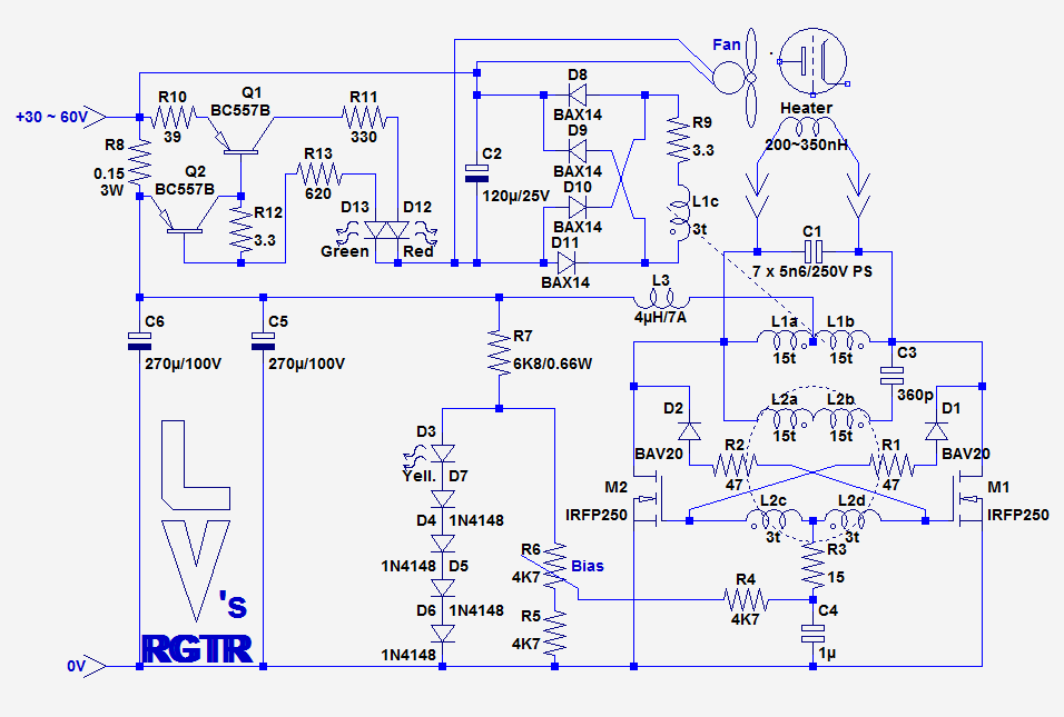
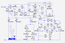
Here is the base schematic:
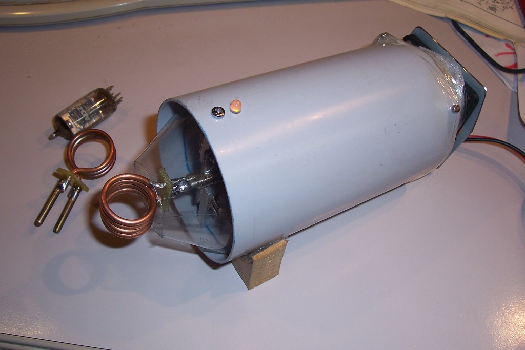
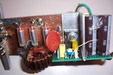
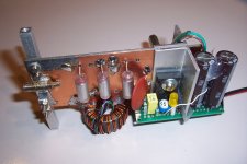
Here is the outlook of the finished instrument:
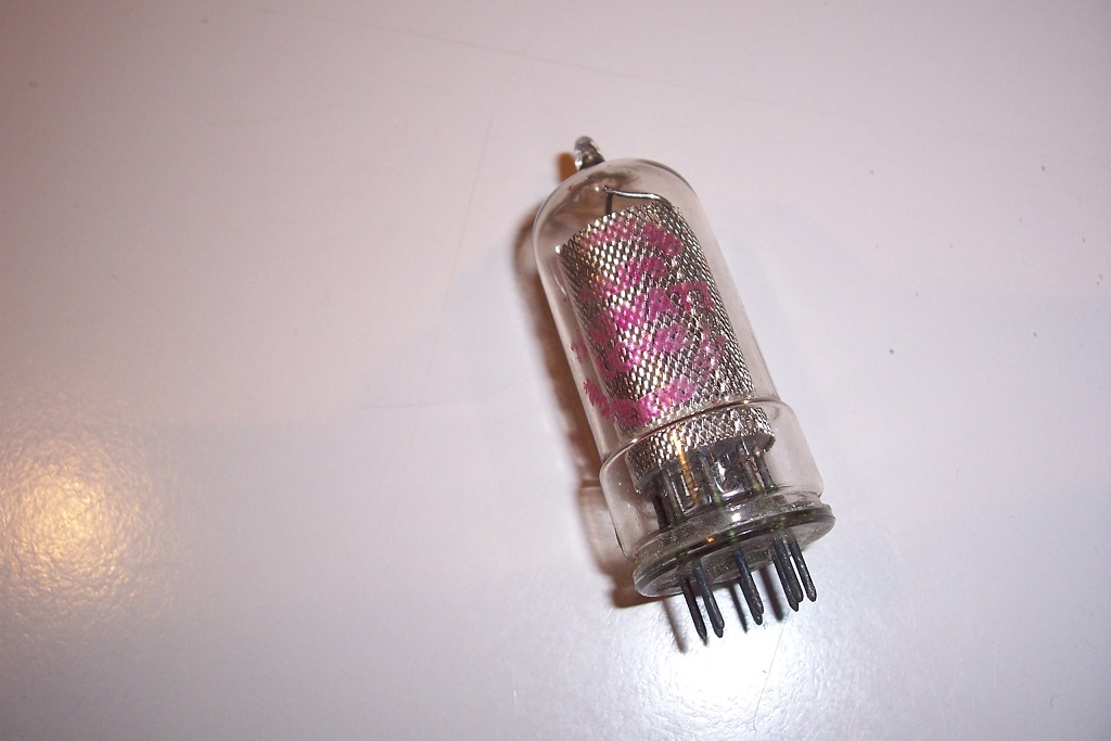
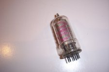
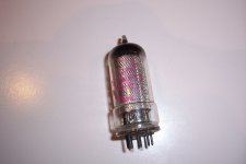
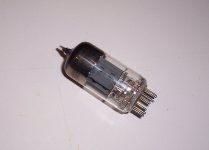
Here is an example of an UCH42 having initially its getter completely spent:
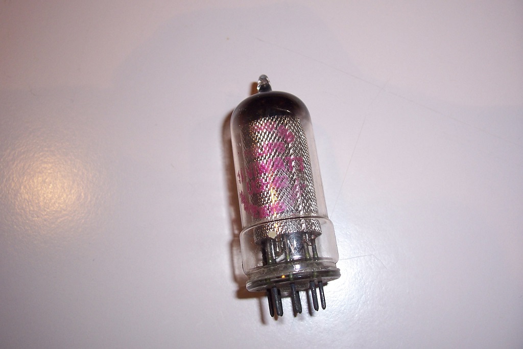
Here is the same valve after treatment:
To be continued.....
Since I have a large stock of used tubes in various conditions, from NOS in the original box to (very!) well used, I felt the need to equip myself with a stable and reliable device for regettering: some of my samples have a bad need for such a treatment, and although I managed to get results by cobbling together an improvised oscillator, it was neither safe nor practical.
Here is a description of the low-cost machine I devised.
It is essentially a Royer oscillator, but with a number of refinements making it universal: the coil head is interchangeable, making it compatible with all sizes and geometries of common tubes.
The electrical output parameters can also be varied in a wide measure, making it practically universal.
I also made an attempt at an aperiodic power driver, essentially a half-bridge driven at HF, and it worked, but the burden on the active elements was immense, due to the fact that the load is mostly reactive, due to the poor coupling between the heating coil and the getter ring.
In the end, I opted for the sensible solution: in a Royer, most of the reactive part of the load is taken care of by the tuning capacitor, easing the burden on active elements.
A regular Royer requires a coil with 5 or 6 connection, which is not practical.
I therefore modified the initial circuit to arrive at 2 connections, which is obviously the minimum possible..
The resulting circuit is significantly more complicated, but it remains manageable, and it is completely safe, deterministic and reliable.
It is possible to make a 2 terminal Royer oscillator much more simply, but it is neither safe nor reliable: relying on direct cross drive from drains for feedback is a recipe for disaster if the oscillator stalls.
With inductive feedback and controlled bias, there is no such risk.
Here is the base schematic:
Here is the outlook of the finished instrument:
Here is an example of an UCH42 having initially its getter completely spent:
Here is the same valve after treatment:
To be continued.....
Attachments

It will last no longer or shorter than the original. Of course, since the initial one has been depleted, it means that gas can find its way into the envelope, and the new layer will continue to react in the same way.This treated getter will works how long?
The amount of "green" getter material initially introduced within the getter structure is vast compared to the tube needs: even a µg or two would be large, considering the high level of vacuum inside the tube.
For example, here is a PCF80 that is been used as a guinea pig for the tests:
You can see that as a result, it been massively overgettered (probably ruining it for good, but anyway it already was in a poor condition)
Here is a short video showing a PCF80 being treated:
YouTube
Before proceeding further, one or two words of caution might be necessary.
The proportion of used tubes actually requiring regettering is small, certainly less than 5%, and from this small percentage, a good proportion is already completely exhausted due to other reasons, thus not requiring treatment.
Regettering should only be attempted on tubes needing it. Attempting to regetter a tube in working order will change nothing at the very best, but could very easily end up ruining it, because of thermal stress and contamination of internal structures if the gettering is excessive.
A tube requiring gettering has:
a) A visible depletion, degradation or absence of the getter layer
b) Electrical symptoms, like abnormal DC conditions, suspicious glowings or arcing.
If both criteria aren't met, don't embark into such an undertaking. Regettering could unfortunately become the new recapping: someting like 80% of recappings are purely frivolous, made to make the recapper feel good, but unfortunately, a significant proportion end up the worst possible way, with a perfectly fine equipment thoroughly ruined.
One last thing to mention: regettering won't yield immediate results. In fact, it may make matters worse initially, because of the turmoil, stress and outgassing it causes to the tube.
Only after a number of hours of baking or operation will things begin to improve: the process of capturing stray gas molecules is slow and requires the right temperature.
Note that there is no published data about gettering, because it was supposed to be done once, at the manufacturing plant, not in the field.
This means that no standards or guidelines exist for such an operation, and for example two identical tubes from different manufacturers may have very different needs in terms of gettering.
This means that each attempt is a different adventure, and carries its own risks....
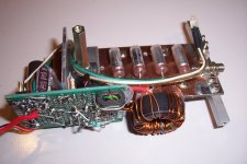
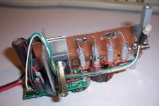
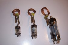
So far, I have built three coil heads, corresponding to the most common sizes of tubes:
Here are some pics of the innards:
Attachments
Around 1.5MHz, very approximatelyWhat frequency does it run at?
Thanks for that: I did notice that Youtube added the "edit" bit to the url, but no matter what I did, it insisted on inserting it, even though the source link from which I copied it didn't have it, so I reasoned that Youtube/Google being so much smarter than us all, I shouldn't edit manually the url after it was pasted. I was wrong: sometimes, Google is just a bit too smart.Your YouTube link seems to go to *your* editing page. (Actually for me it goes to *my* editing page.)
Code:youtube.com/edit?o=U&video_id=Zibnaj4fXlE -private edit youtube.com/watch?v=Zibnaj4fXlE --- public view
We want this link: YouTube
youtube.com/watch?v=Zibnaj4fXlE
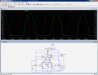
Here is an approximate sim of what's going on in the oscillator. The real circuit performs better, fortunately.
L6 is the heater coil, coupled to the getter ring L9, symbolised by a turn shorted by a resistor, L11 L10 is the feeding/symetrising autoformer, and L1 L2 L4 L5 is the gate drive transformer.
Initially, the gate windings were taken directly from the power autoformer (as can still be seen on the pics above), but the leakage inductance was excessive: the circuit is extremely dependent on a minimal gate inductance, and I had to add a specific low-power transformer, built on a two-hole VHF ferrite core.
The three secondary turns are embedded in the middle of the primary winding, and a series capacitor of 360pF (not present in the sim) compensates for the residual leakage.
Attachments
Ebay - Induction Heating Power Supply Driver
diy-induction-heater.htm
Dan.
diy-induction-heater.htm
You will need a brain that functions reasonably well to make this project safely. If you are one of those people who is known by your friends as "a bit thick", then congratulations on being able to use a computer and navigate to this page, but unfortunately this project is not for you. It can be very dangerous to build an induction heater, so if you are new to electronics, you should get someone to help you make it. Approach things logically; If it is not working, check the components used are not faulty, check connections are correct, read this whole article and all the comments, search Google if you do not understand any of the terms, or read through our Learn Electronics section. Remember: Hot things will burn you and can set things on fire; Electricity can electrocute you and also cause fire. Put safety first.
Dan.
Last edited:
These are cheap, but I don't think they will be usable for regettering: from what I see, they use a total of 0.66µF tuning capacitors, and the coil must have an inductance of 1µH or thereabout, which means that the output frequency will be in the low 100's of kHz, much too low for the purpose.
They will easily heat magnetic, rod like objects, but if the Curie point is reached or if the shape is flatter, it will be difficult to reach a sufficient temperature.
Because of the weak coupling between the getter ring and the coil, and the need to reach high temperatures, the dΦ/dt needs to be high, meaning high current intensities at high frequencies (even the 1.5MHz I used is marginally low).
In addition, they accumulate all the features I wanted to avoid: direct feedback from drain cross-coupling, supply through separated, uncompensated chokes having to bear both high DC and high AC, etc.
But trying them costs near to nothing, so why not
diy-induction-heater.htm
The majority of the projects presented in this section of the forum is probably far more dangerous....
The validity of this approach is questionable.
Gettering material is not metallic barium, but rather barium nitride. Getter is fired while a tube is still on vacuum pump. Barium nitride decomposes into metallic barium and nitrogen. Barium is deposited on the glass, and nitrogen is removed by the pump, after which the tube is sealed. Re-activating the getter may restore the flash, but it will also release nitrogen, making the tube gassier than it used to be.
Old style magnesium/aluminum getters may be more amenable for restoration because initial gettering material is pure metal.
- Status
- This old topic is closed. If you want to reopen this topic, contact a moderator using the "Report Post" button.
- Home
- Amplifiers
- Tubes / Valves
- A universal regettering station