Thank you for the answer.
Something to look at. I will look at the 7805 data sheet and check the capacitor values. Maybe consult tentlab for a couple of DC filament supplies for 300B.
The choke I was looking at was this one:
Welter Audio Electronic Seit 1975
It is rated as 200 mA.
Each 300B draws approx 60 mA bias current.......but your calculation is 120 mA for each tube? .....do they draw double when full loaded?
DR3 choke......
The values of the two caps after the rectifier for the 7805 are 4700uF/10V and the cap connected to the output of the 7805 is 330uF/40V.
I was good I tried the "Duncan PSUD2" simulator.
I does not work at all just inserting a 10H/130 ohm choke.
The voltage drop is way to high. I must find another solution. First I will measure the ripple using a scope to see how bad the ripple is.
Hope my main problem is the AC on the 5V DC......and maybe the wires.
It works better by changing the RC to a LC. 200 mV ripple goes down to 10-15 mV......approx.
The 8V ripple measured using a multimeter was wrong. I could see that using a scope. But the LabNation scope showed some stranges values probably caused by the high voltages.
It worked better when I measued the 5V DC. It looked worse than expected.
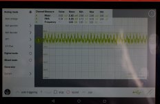
I have attached a picture of the scope screen. It is 50 Hz noise....1V pp.
How can it be 50 Hz?
It fits fine with what I hear in the speaker......it sounds like 50 Hz.
If it was the 7805 regulator ripple it would be 100 Hz?
Think the 5V DC is my main problem and I should concentrate solving this first.
The 8V ripple measured using a multimeter was wrong. I could see that using a scope. But the LabNation scope showed some stranges values probably caused by the high voltages.
It worked better when I measued the 5V DC. It looked worse than expected.
I have attached a picture of the scope screen. It is 50 Hz noise....1V pp.
How can it be 50 Hz?
It fits fine with what I hear in the speaker......it sounds like 50 Hz.
If it was the 7805 regulator ripple it would be 100 Hz?
Think the 5V DC is my main problem and I should concentrate solving this first.
Attachments

I think the measurements from yesterday was not right. The probe had a bad connection so it picked up hum from the mains. I saw this also tonight.
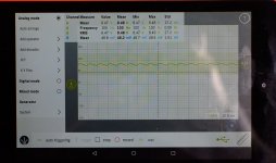
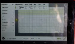
I have made new measuremens which are more correct.
Measurements are:
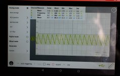
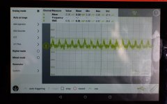
Input to 7805 in both DC and AC mode for left channel.
To my eye it looks ok.
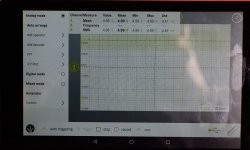
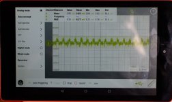
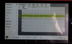
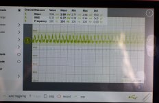
300B filament in both DC and AC mode for left and right channel.
In AC mode some noise is visible. Should it be less?
I have made new measuremens which are more correct.
Measurements are:
Input to 7805 in both DC and AC mode for left channel.
To my eye it looks ok.
300B filament in both DC and AC mode for left and right channel.
In AC mode some noise is visible. Should it be less?
Attachments
-
 DSC_3678_DC_7805_in_left.jpg267.7 KB · Views: 164
 -
 DSC_3679_AC_7805_in_left.jpg301.8 KB · Views: 146
 -
 DSC_3682_DC_300B_filament_right.jpg269.1 KB · Views: 147
 -
 DSC_3683_AC_300B_filament_right.jpg232 KB · Views: 160
 -
 DSC_3684_DC_300B_filament_left.jpg287.2 KB · Views: 37
 -
 DSC_3685_AC_300B_filament_left.jpg978.1 KB · Views: 49
OK.....just as a first "try" to check if it has any impact.
There is a delayed B+ "turn on" (45 sec).
How much is that needed?
If I could remove the 555 timer board then the 400V AC wires could be kept better aside and wires could be shorter.
Does it mean a lot for the lifetime of the tubes that you turn on heater first and then after 45 sec. turn on the B+?
OK.......next step will be to unbundle the wires. Now I also have documentation so a change can be verified.
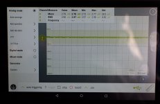
Some results after the bundle has been broken and 400AC wire pulled away from the others.
It seems the noise signal is a bit cleaner as the scope now can measure 100 Hz.
All measurements are with probe on 300B filament.
There is a measurement with no power cord plugged in.
Then there is a measurement with only power cord plugged in but no power on trafo. It seems there is a bit of noise before the power trafo is turned on.
Chassis is connected to safety ground and cord has safety ground but no saftety ground in the installation (normal here not to have safety ground in the living rooms). So safety ground is "floating" in the power cord). Can that cause hum?
I measure with a headphone box connected as this has 2 x 8.2 ohm resistors. When I connected the headphone the noise signal was reduced a bit.......why? .....the headphone is a very small load compared to the two 8.2 ohm resistors.
It seems the hum is a bit less.....subjective when I took the headphone on.
Maybe a re-wire project can reduce it further.
There is a delayed B+ "turn on" (45 sec).
How much is that needed?
If I could remove the 555 timer board then the 400V AC wires could be kept better aside and wires could be shorter.
Does it mean a lot for the lifetime of the tubes that you turn on heater first and then after 45 sec. turn on the B+?
OK.......next step will be to unbundle the wires. Now I also have documentation so a change can be verified.
Some results after the bundle has been broken and 400AC wire pulled away from the others.
It seems the noise signal is a bit cleaner as the scope now can measure 100 Hz.
All measurements are with probe on 300B filament.
There is a measurement with no power cord plugged in.
Then there is a measurement with only power cord plugged in but no power on trafo. It seems there is a bit of noise before the power trafo is turned on.
Chassis is connected to safety ground and cord has safety ground but no saftety ground in the installation (normal here not to have safety ground in the living rooms). So safety ground is "floating" in the power cord). Can that cause hum?
I measure with a headphone box connected as this has 2 x 8.2 ohm resistors. When I connected the headphone the noise signal was reduced a bit.......why? .....the headphone is a very small load compared to the two 8.2 ohm resistors.
It seems the hum is a bit less.....subjective when I took the headphone on.
Maybe a re-wire project can reduce it further.
Attachments
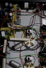
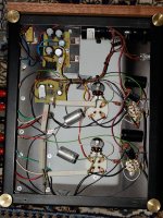
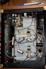
I finished first part of the re-wire project. A picture is attached before and after. Think it looks "more correct" now. Will test it tomorrow. I removed the "soft start print" as this was "stealing" power from the 6.3V heater via the quite long gray twisted wire.
I now use the "on/off" switch to manually with on the high voltage. The heater voltage are switch on as soon as the power cord is connected. I wanted to make it as simple as possible.
I know that the switch on the front which before was the main 230V AC switch should be a 400V AC version. But I assume it will be ok for testing as the 400AC only is about 200 mA (probably less). The switch is rated 250V AC/ 5A.
We will se what happens and interesting if this rewiring causes less hum. I expect there will still be hum and that I need to switch to more "silent" 5V DC filament devices for the 300B and maybe need reduce the ripple on the high voltage.
Attachments
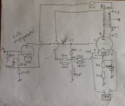
I have added a simplified schematic. Can anybody tell what the purpose is for the 2x150k from the cathode of the 300B? I can see there is a "DC purpose" defining the anode voltage for the ECC83 but what is the "AC purpose"? Is it a local feedback loop for the 300B?
Attachments
I have made some measurement without any tubes inserted. I now have a manual switch to couple the 400V AC to the rectifier. This switch was turned off so no B+.
On the output I have a headphone adapter box just to have load on the output. There is still 50 Hz hum without any tubes inserted. About 4 mV RMS measured with the scope. On the primary of the OT there is about 50 mV of 50 Hz hum.
I guess it must be a 50 Hz magnetic filed from the power transformer?
The chassis is steel.
There is one star ground connected direct to the chassis. Then there is the safety ground also connected to the chassis close to the input main plug.
Could it be an idea to try to isolate the "audio ground" from the chassis via a 10 ohm resistor and a 0.1 uF capacitor?
Any other tricks?
I have added a simplified schematic. Can anybody tell what the purpose is for the 2x150k from the cathode of the 300B? I can see there is a "DC purpose" defining the anode voltage for the ECC83 but what is the "AC purpose"? Is it a local feedback loop for the 300B?
There is only a dc-purpose for the resistor network: The 100µF cap means that there is only a dc voltage at the bias-node. There is no ac-feedback.
I think it was a problem that one side of the primary of the OT is floating. I have measured that it picks up some 50 Hz noise. Think I need to insert tubes or ground the floating end of the primary via a resistor. I may try that or just insert the tubes to test the new layout/simplification of the wiring. Will do that next week. Now I know that everything is ok after the "re-design" with manual delay of B+ via an on/off switch.
There is only a dc-purpose for the resistor network: The 100µF cap means that there is only a dc voltage at the bias-node. There is no ac-feedback.
Thank you for the answer. I am still new to tubes so a steep learning curve. The AC signal path of the 300B from the anode to cathode is via the 100 uF capacitor to ground (I know the electrons are going the opposite direction)?
The purpose of the 2 x 150k must be to define the anode voltage for the ECC83? .....in principle this could have been done without involving the cathode capacitor of the 300B (e.g. just finding the right resistor divider from B+ to ground)?
With the B+ off, and ripple still present, it sounds like the filament transformer is "talking" to the output transformer.
The steel chassis aggravates this. Even with an aluminum chassis, it is necessary to have the correct angular orientation of the windings of the OPT to power transformer(s) and filter choke(s). It is also necessary to have enough space between the OPT and power transformers and filter chokes.
Once there is that kind of ripple, it is unlikely that the shape of ripple at the input tube will be the same shape, but opposite phase as the magnetically coupled ripple.
It is better to prevent the ripple in the first place; cancellation techniques usually only work somewhat.
<cut>
The purpose of the 2 x 150k must be to define the anode voltage for the ECC83? .....in principle this could have been done without involving the cathode capacitor of the 300B (e.g. just finding the right resistor divider from B+ to ground)?
It's a better circuit than just setting up the driver's anode voltage. The resistor network also allows the driver triode ECC83 to help stabilise the 300B anode current. (If the 300B draws more current, the ECC83 anode voltage increases, and the driver then increases current, lowering the 300B current).
This dc-stable configuration of driver and 300B output has a big advantage: it allows dc-coupling between driver and 300B grid. Many power-triode designs use capacitor-coupling to the grid, which easily leads to the capacitor acquiring dc-voltage during large-signals. (web search "grid blocking distortion", for more).
DC-coupling solves the blocking distortion problem more simply than adding a power-FET grid driver, and reduces the risk of grossly overdriving an expensive 300B. But, at the cost of the very high anode voltage supply.
With the B+ off, and ripple still present, it sounds like the filament transformer is "talking" to the output transformer.
The steel chassis aggravates this. Even with an aluminum chassis, it is necessary to have the correct angular orientation of the windings of the OPT to power transformer(s) and filter choke(s). It is also necessary to have enough space between the OPT and power transformers and filter chokes.
Once there is that kind of ripple, it is unlikely that the shape of ripple at the input tube will be the same shape, but opposite phase as the magnetically coupled ripple.
It is better to prevent the ripple in the first place; cancellation techniques usually only work somewhat.
What I see without tube installed is mainly 50 Hz at the OT. B+ not on means that there is a switch before the rectifier. The 400V AC is on. I tried to connect the two wires to the primary of the one OT together. Then signal dropped from 2 mV to 0.6 mV AC at the output. We will see when I insert the tubes again after re-wiring. If there is still 50 Hz it is probably the PT talking to the OT. I have ordered some mu-metal foil I will try to place inside the PT housing. I have no idea if that can reduce the 50 Hz but it will probably not get worse. I have also ordered Pete Millett DC filament supply and ordered components for it also. A choke instead of the filter resistor for the B+ could also be an update.
I discovered that the wires to the primary for one OT was in a wire bundle where also the shielded input wires were. I have corrected this.
I also discovered that the star-ground which was in two pieces was just pressed together by the nut of the "ground chassis screw". I have soldered wires on so a bad connection between the two parts can't make a "ground loop".
- Status
- This old topic is closed. If you want to reopen this topic, contact a moderator using the "Report Post" button.
- Home
- Amplifiers
- Tubes / Valves
- 300B SET amp measurements without tubes installed