wow this is exactly what I want to do.
100k potmeter is it the one with adjustable knob or trimmer?
5 x 100K OHM TRIMPOT TRIMMER POTENTIOMETER 3362 3362P | eBay
100k potmeter is it the one with adjustable knob or trimmer?
5 x 100K OHM TRIMPOT TRIMMER POTENTIOMETER 3362 3362P | eBay
VU meters are in db's so there logarithmic. Volt meters are not. Don't use a volt meter it will not work properly. if your amp has some power (100watts) the VU meter needle will hardly move at normal levels so you might want it to be adjustable.
VU / dBm meters +are+ (AC) voltmeters, there is no difference in the windings, magnets and so on. The main difference are the +scale markings+.
VU and dBm meters have log scales, standard voltmeters have linear scales. A dBm meter is just an AC voltmeter with a specified full-scale voltage and a log scale. Otherwise, there is simply no difference with the exception of the VU meter, which as I mentioned, has both the log scale and a specific needle damping factor built-in which helps to average out levels. This damping may be accomplished with friction (a viscous damper) or electronically (with a capacitor) - I'm not sure which approach is more common.
If you connect a VU meter in parallel with a dBm meter, they will both read the same level with the same input. The differences are only apparent when they are driven with a rapidly varying signal (audio, speech). You will see the VU is less twitchy than the dBm meter, due to the stronger damping in the former.
If you are going to switch two tube amps to one set of speakers, you need to have an additional set of resistors to switch across the amp not driving the speakers. You also need to use make before break switches.
The reason is that a tube amp with no load on the output sees near infinite impedance driving the transformer. You will create over-voltage transients which can damage the output transformers if there are no loads.
The reason is that a tube amp with no load on the output sees near infinite impedance driving the transformer. You will create over-voltage transients which can damage the output transformers if there are no loads.
If you are going to switch two tube amps to one set of speakers, you need to have an additional set of resistors to switch across the amp not driving the speakers. You also need to use make before break switches.
The reason is that a tube amp with no load on the output sees near infinite impedance driving the transformer. You will create over-voltage transients which can damage the output transformers if there are no loads.
The simple way around this, is to just add fixed high-value (relatively) resistances to the switching box inputs, which also eliminates the need for MBB switches.
Install something like a 1K 2W across each set of speaker input terminals, so that any amp channel connected to the box always has at least that 1K load across the output. When you switch-in a speaker load, that load will be in parallel with the 1K - but due to the very large ratio (like 1000:8 ohm aka 125:1) only 0.8% of the power is lost to the 1K part.
With 4R speakers, the loss is 0.4%, and 1.6% with 16R. Raise the value from 1K to 2K, and this drops off by half again. Not sure how high you can safely go, but it's pretty high.. around 5-10K I'd think, but that should be checked out.
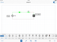
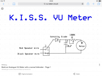
This page provides an excellent tutorial on the kind of metering that you're looking for: A simple passive logarithmic VU-meter
This page provides an excellent tutorial on the kind of metering that you're looking for: A simple passive logarithmic VU-meter
I haven't read the whole tutorial, but here's a salient point:
Professional or high-end amplifiers have good meters with logarithmic converters built with many op-amps and lots of parts
Yes, exactly. If you need a log scale indication from any standard electro-mechanical meter, there are two ways to achieve it - either you use a standard linear meter with a log-converting circuit, or you use a standard meter movement with a log scale. The dB meter pictured near the top of the article is the latter - you can see that the scale is logarithmic. On the low end of the scale, one minor division is 5dB - whereas on the high end of the scale, one minor div is 1 dB.
It seems that the article offers a simpler, passive method for creating a log response on a standard meter. Typical caveats apply, as with any passive circuit - you're going to lose voltage (gain) across the diodes, resistors, etc. But ultimately, if the correct meter movement is chosen, this isn't necessarily a problem.
(It's also worth pointing out that +all+ mechanical meters are, in fact, ammeters. It's armature current that produces the field which drives the pointer. If that current is (relatively) low, then it may be called a Voltmeter - if it's relatively higher, then it may be called an Ammeter.)
Last edited:
Meters are an interesting subject.
My first meter was a 0-1 mA DC meter. It was a D'Arsonval movement.
So, it was a current meter.
It had 50milli Ohms of resistance.
But that also makes it a 50mV DC voltmeter.
A 10k Resistor in series with the meter made it a 10VDC meter.
A 100Amp shunt across the meter produced 50mV @ 100A, and that made it a 100ADC meter.
Resistors and a bridge rectifier made it an Average responding AC meter
(which could be calibrated in RMS, as long as the AC is a sine wave).
- Status
- This old topic is closed. If you want to reopen this topic, contact a moderator using the "Report Post" button.
- Home
- Amplifiers
- Tubes / Valves
- Advice for Vu meter