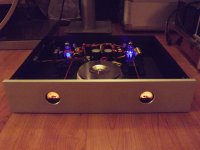
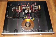
I am new to tube amp world but love the sound. I want to make a A/B switcher for 2 set speakers but hook up to 1 tube amp. I want it to be fancy so I like to add a Vu meter  . However, I am not sure it is safe to use speaker output to this product. Please advice. thank you
https://www.amazon.com/gp/product/B00WUA3RNU/ref=ox_sc_act_title_1?ie=UTF8&psc=1&smid=ADPE7GPX91ORE
https://www.amazon.com/gp/product/B00WUA3RNU/ref=ox_sc_act_title_1?ie=UTF8&psc=1&smid=ADPE7GPX91ORE
I just found on eBay have more info. Please help.
2pcs Panel VU Meter Warm Back Light Recording TR-35&Audio Level Amp driver board | eBay
2pcs Panel VU Meter Warm Back Light Recording TR-35&Audio Level Amp driver board | eBay
Thank you. Just to make sure I got it right. I need these parts?
VU2 Stereo VU Buffer Kit
SEW 315 VU Meter (2)
VU2 Stereo VU Buffer Kit
SEW 315 VU Meter (2)
Perhaps I missed something.. but where do you plan to connect this meter, and what do you hope it will tell you? VU meters are normally used to indicate line-level signal strength, referenced to a particular impedance, such as 0 VU (or 0 dBm) = 1mW @ 600R.
Yet it sounds to me like you want this meter in parallel with the speaker output(s)? But again, what do you hope it will tell you, other than the instantaneous (or slightly averaged, with VU meter) voltage at the speaker terminals?
Yet it sounds to me like you want this meter in parallel with the speaker output(s)? But again, what do you hope it will tell you, other than the instantaneous (or slightly averaged, with VU meter) voltage at the speaker terminals?
Hi, It will connect Speaker output from Tube amp. I am making 2 Channel A/B Switch speaker. I want a simple Vu meter just to have cool effect . As long they needle move along with music is fine, I does not need to be accuracy.
I am new to this , just hope something simple for add on a small project.
Thank you.
I am new to this , just hope something simple for add on a small project.
Thank you.
Last edited:
https://www.youtube.com/watch?v=WxiaxlZfIL8
http://www.ebay.com/itm/Power-Ampli...223202?hash=item19e65fd7a2:g:-OgAAOxyhodR0SsA
this is same as ebay I post above, I just want to be sure they dont have bad effect to Tube amp or worse damange.
http://www.ebay.com/itm/Power-Ampli...223202?hash=item19e65fd7a2:g:-OgAAOxyhodR0SsA
this is same as ebay I post above, I just want to be sure they dont have bad effect to Tube amp or worse damange.
Last edited:
If all you want is a meter, or pair of meters to "bounce" along with the music, then your options are plenty. For each channel, you just need an AC voltmeter (not an ammeter) that has an appropriate range. For instance, if you have a meter that reads 0-20V AC (rms) this would indicate 50W into 8R at full scale (20V). But you could also use a meter that reads 0-5V AC or even 0-1V AC (rms) and use a series resistor divider to calibrate the meter such that it reads full scale at the amp's max output.
so I can just buy AC voltmeter hook direct to speaker out then good to go? 0-20V , Do you think the link will work fine connect to speaker out from amp?
AC 0-30V Round Analog Voltmeter Voltage Panel Meter AC DH52 Directly Connected
AC 0-30V Round Analog Voltmeter Voltage Panel Meter AC DH52 Directly Connected
so I can just buy AC voltmeter hook direct to speaker out then good to go? 0-20V , Do you think the link will work fine connect to speaker out from amp?
AC 0-30V Round Analog Voltmeter Voltage Panel Meter AC DH52 Directly Connected
Yes, that's the basic idea.. though, you're going to have a hard time driving a 30V meter to full-scale with an 8R load. That would be 112W output.. which is good, if you have a 100W/chan amp, but not so good if you have a typical 15W/chan amp which will only drive 11V into an 8R load. So at full power, your 15W amp would max the meter out at 11V (1/3 full scale).
So if you want more meter movement, you're better off using a lower-range meter (like 0-1V / 2V / 5V / 10V) and then an external series resistor (or a pot is OK) to calibrate the meter to indicate what you want when your amp is at 1W, half-power, full-power.. or whatever suits your fancy.
Last edited:
This version seem can be adjust the Vu meter. I think I will give this a try. THanks
https://www.aliexpress.com/item/VU-...lt&btsid=5ae63d34-78a1-429d-87d7-9da024ec1c98
https://www.aliexpress.com/item/VU-...lt&btsid=5ae63d34-78a1-429d-87d7-9da024ec1c98
Just to have a bouncing needle is fine.
It can look cool.
As to determining relative power, volts and power are not 1 to 1.
An AC voltmeter gives you volts.
This is a linear function.
Power is Volts squared.
This is a square law function.
Oh, totally. But per the OP, it seems this is all about creating a display, purely for effect.
One common approach to a meter for +display+ purposes is to use an SPDT switch to select either of two different external series resistor values such that the meter hits full-scale at:
- R1 (low range) = 1W into chosen load
- R2 (high range) = Full power into chosen load
This way you can get some kind of semi-meaningful info from the meter in either range, while also ensuring plenty of "bounce" at even low-ish power levels. So if we have a 15W amp driving an 8R load, you would want the meter calibrated like so:
- Low range = f/s @2.83V RMS (1W @ 8R)
- High range = f/s @ 10.95V RMS (15W @ 8R)
This means that if we want full-scale operation in the low range, the meter must be built for full-scale at 2.83V RMS minimum. Best choice for an off the shelf meter, in this case, might be a 1V or 2V full-scale meter. If the meter is more than 3V full scale, you'd never get full deflection in the low range - but that might be OK too. And this doesn't even begin to account for meter bandwidth (frequency response)..
Again, it's just a display. See the needle bounce? That means it's working.
Last edited:
Yup I put 2 DPDT switch for each channel. My tubeamp rated at 60W/Channel. I hope this kit is ok to read the load from this amp. I watch the video on youtube , needle quite jumpy alot, I hope mine dont do that. Someone recommend add capacitor across .
https://www.youtube.com/watch?v=PSU7SVg8O2Y
DPDT Heavy Duty Toggle Switch
https://www.youtube.com/watch?v=PSU7SVg8O2Y
DPDT Heavy Duty Toggle Switch
Most Vu meters have a rectifier (half wave, or full wave bridge, I don't know).
There is probably at least one resistor.
The meter is typically a D'Arsonval DC movement.
I don't know if there is, or is not, a capacitor across the meter movement.
But for expensive Vu meters, the total of all the circuitry and meter movement
is supposed to give very specific characteristics of rise, undershoot/overshoot, and fall.
Adding an (maybe extra) capacitor will certainly change these characteristics.
That might give the "look" of the meter movement you desire.
I agree with the idea of having ranges of sensitivity.
This board have adjustable for both Vu meter
https://www.aliexpress.com/item/VU-...lt&btsid=5ae63d34-78a1-429d-87d7-9da024ec1c98
https://www.aliexpress.com/item/VU-...lt&btsid=5ae63d34-78a1-429d-87d7-9da024ec1c98
For a poweramp you do not need any active electronics.
Just buy any Vu or power meter and put 1 diode and a resistor in serie with the meter. Tune the resistor for best performance. Can also use 100k potmeter instead of resistor.
Just buy any Vu or power meter and put 1 diode and a resistor in serie with the meter. Tune the resistor for best performance. Can also use 100k potmeter instead of resistor.
Attachments
Last edited:
- Status
- This old topic is closed. If you want to reopen this topic, contact a moderator using the "Report Post" button.
- Home
- Amplifiers
- Tubes / Valves
- Advice for Vu meter

