Thank you. I plan on having a switch for eternal speakers.
You need something that will work well fed only 5 WPC. If the speakers are below mid 90s in sensitivity, you rate to be unhappy.
You need something that will work well fed only 5 WPC. If the speakers are below mid 90s in sensitivity, you rate to be unhappy.
I have a few high eff drivers around to play with.
")
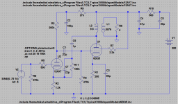
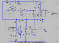
I don't know the Z of the OPTs in the console but for sims I used an inductance ratio of 1250:1 which if I am doing it right gives 5k load for 4 ohm speakers yet I can't get more than about 2.5 Watts before clipping (4.25Vpk). Output tube is biased for just over 11W at idle. ???
Kind of take that back. Can get almost 4W with the cathode FB.
Kind of take that back. Can get almost 4W with the cathode FB.
Last edited:
Artifact?
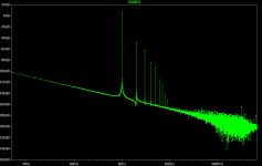
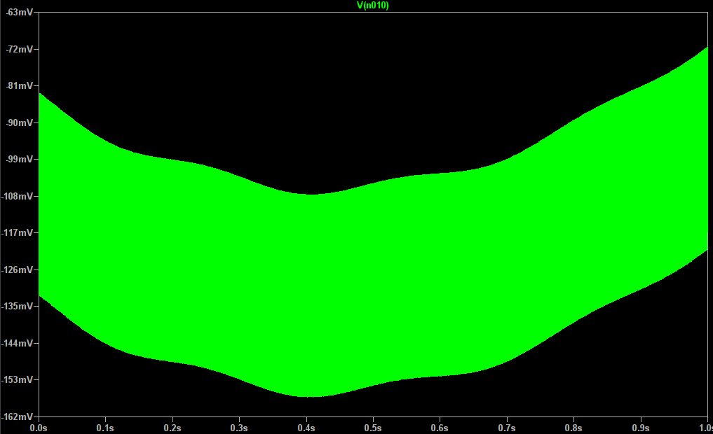
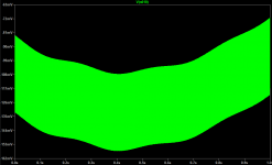
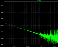
Is this an artifact of the simulation or am I missing something? I shorted input to second AX7 to make sure that it wasn't a loading issue. Signal plotted is the output of the RIAA filter. The PS voltage stabilizes immediately so that isn't it.
Is this an artifact of the simulation or am I missing something? I shorted input to second AX7 to make sure that it wasn't a loading issue. Signal plotted is the output of the RIAA filter. The PS voltage stabilizes immediately so that isn't it.
Attachments

Grrr.
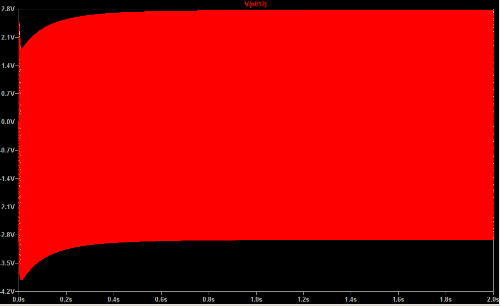
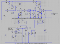
OK, this is crazy. Both the PA and the phono sim fine separately but connect them together and the intermediate signals go wacko. If I short the input to the PA (U2) and disconnect it from the CF output the signal at the output of the CF and the signal at the output of the shapping circuit are perfect. When I hook up to the PA section it goes nutso. This trace is the output of the filter section at the grid stopper of the second stage.
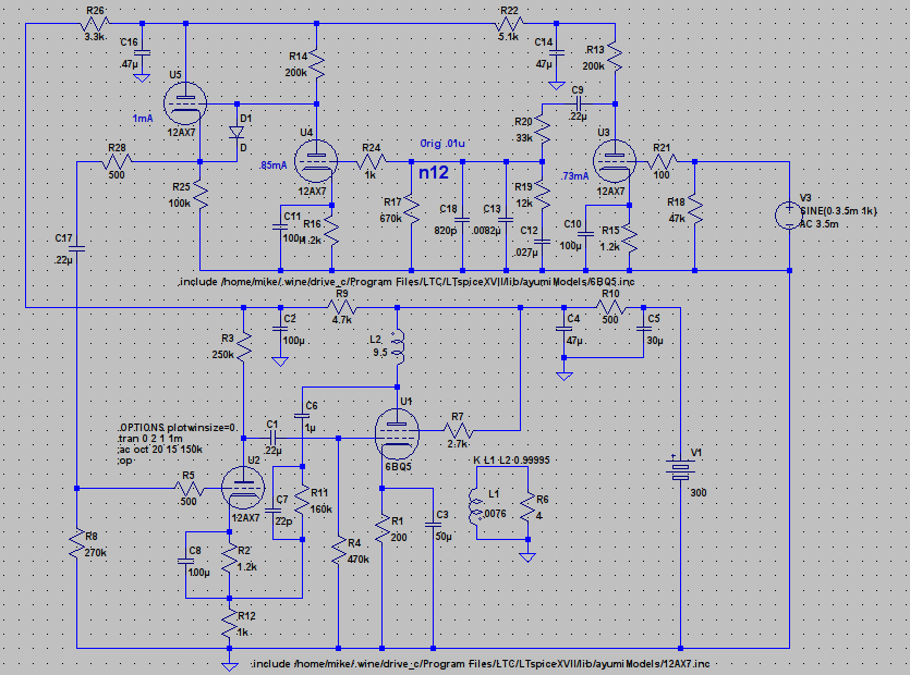
Removing the cathode stopper seems to help some but I still get this at the input to the PA. Is it mayby a reaction to the FB in the PA VAS cathode circuit?
New info. At least a part of it was that I forgot to put in volume control and was overloading PA. Cleans up a lot when I do that. Still have some hunting inside the FB loop but probably can get it right if I fiddle enough. Need more input headroom to PA and probably lower FB ratio.
OK, this is crazy. Both the PA and the phono sim fine separately but connect them together and the intermediate signals go wacko. If I short the input to the PA (U2) and disconnect it from the CF output the signal at the output of the CF and the signal at the output of the shapping circuit are perfect. When I hook up to the PA section it goes nutso. This trace is the output of the filter section at the grid stopper of the second stage.
Removing the cathode stopper seems to help some but I still get this at the input to the PA. Is it mayby a reaction to the FB in the PA VAS cathode circuit?
New info. At least a part of it was that I forgot to put in volume control and was overloading PA. Cleans up a lot when I do that. Still have some hunting inside the FB loop but probably can get it right if I fiddle enough. Need more input headroom to PA and probably lower FB ratio.
Attachments
Last edited:
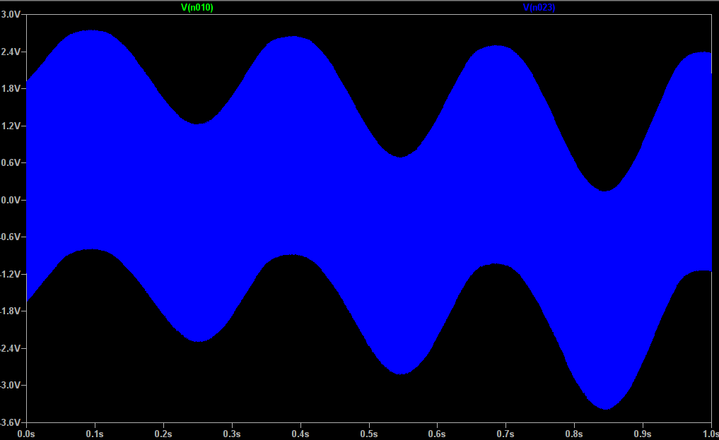
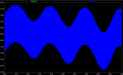
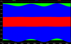
Plate to plate seems to be easier to control so I am playing with that some. Low level signal gives nice stable output but in between the last two stages and the input to the penultimate stage both show wandering voltage. It is not easy to see in the input voltage but it is there (a few 10ths of a volt). I wouldn't be surprised to see some unusual wave forms in between but why the wandering DC offset?
Red is input to PA, Blue is input to 6BQ5, Green is OPT secondary.
P.S. This is about 15dB FB.
Red is input to PA, Blue is input to 6BQ5, Green is OPT secondary.
P.S. This is about 15dB FB.
Attachments
Last edited by a moderator:
Resurrecting this old thread as I think I have a plan.
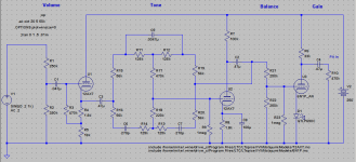
I have a SE KT88 amp, a pair of nice 8" woofers and a pair of 4" wide-range Mark Audio drivers on hand. I can mount these in the cabinet, reserve the OPTs for another application and use the chassis to make a nice preamp with active tone controls.
I have a SE KT88 amp, a pair of nice 8" woofers and a pair of 4" wide-range Mark Audio drivers on hand. I can mount these in the cabinet, reserve the OPTs for another application and use the chassis to make a nice preamp with active tone controls.
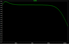
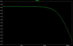
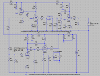
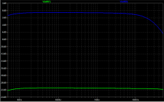
This could be done with the existing sockets on the original amp chassis. There would be plenty of B+ and heater power to supply an outboard phono amp. I am a little surprised at the HF loss in the final gain stage (I presume this is Mr. Miller showing up) but -3dB is still at 30kHz which is still an octave and a half higher than I can hear.
I could try some NFB around the last stage or some other tubes. I have 12AY7, 12AX7, and 12AU7 on hand. The KT88 power amp is a little short on gain but I suspect even the 12AU7 would have plenty of gain for this application.
I could try some NFB around the last stage or some other tubes. I have 12AY7, 12AX7, and 12AU7 on hand. The KT88 power amp is a little short on gain but I suspect even the 12AU7 would have plenty of gain for this application.
Attachments
Last edited by a moderator:
Further refining the concept Take a look at the chassis.
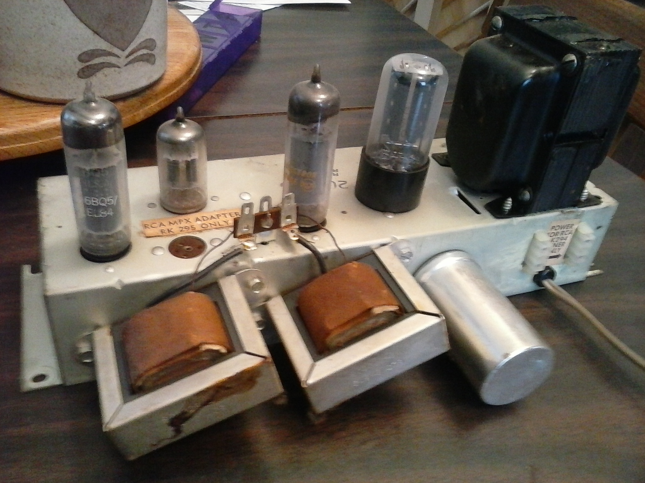
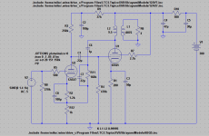
The chassis has an octal socket for the rectifier and a connector for an optional demux. I could use silicon rectifiers and use the octal socket for the output gain stage using a 6SN7 and use the demux connection point for another 9 pin mini. So I could have two 9 pins for the tone control, the octal for the final gain and two 9 pins for a sub-woofer crossover and output. Since I would not be using the 5V winding for the rectifier it could be used for a cooling fan for the power amp as the PT on the PA chassis runs a little on the warm side.
The chassis has an octal socket for the rectifier and a connector for an optional demux. I could use silicon rectifiers and use the octal socket for the output gain stage using a 6SN7 and use the demux connection point for another 9 pin mini. So I could have two 9 pins for the tone control, the octal for the final gain and two 9 pins for a sub-woofer crossover and output. Since I would not be using the 5V winding for the rectifier it could be used for a cooling fan for the power amp as the PT on the PA chassis runs a little on the warm side.
- Status
- This old topic is closed. If you want to reopen this topic, contact a moderator using the "Report Post" button.
- Home
- Amplifiers
- Tubes / Valves
- Getting Started On RCA Console I picked up