I'm interested in this thread for use as a phase splitter between a 4P1L line/driver stage and PP 4P1L outputs. I would need a schematic since I only have knowledge of tubes - haven't studied solid state at all. Is there a simple LND150 solution such as Tubelab posted?
I'd be grateful for some help here!
In a phase-splitter, treat the MOSFET just like a valve, the gate voltage sets the bias just like a valve with the exception the voltage difference between Source and Gate will be a little higher (couple of volts) depending on MOSFET to the Cathode/Grid of the valve it replaced, trim the load resistors for desired current.
In some ways--A MOSFET is like a perfect valve...
Any progress on this thread?
It would be nice to see some schematics showing implementations.
Andy,
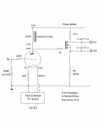
Hop over to AA and check out Jeff Yourison's 6Y6 amp. Jeff used the IRFBC20 as a "concertina" phase splitter.
Thanks for the link. Normally with a tube concertina I've seen equal resistor values top and bottom. I guess because typically a resistor was used in the plate of the preceding tube, so the concertina's grid was about half the voltage of the B+.
If this SS concertina were used with a preceding stage using a plate choke the situation would be different. Just wondering how to proceed with a setup where the gate of the device would be virtually at the same voltage as the HT?
If this SS concertina were used with a preceding stage using a plate choke the situation would be different. Just wondering how to proceed with a setup where the gate of the device would be virtually at the same voltage as the HT?
Attachments
Thanks for the link. Normally with a tube concertina I've seen equal resistor values top and bottom. I guess because typically a If the two outputs should give the same voltage ( which is a requisite for an amp) then the source and drain resistors must be equal.
The suggested schematic don't work that way,
The suggested schematic don't work that way,
Last edited by a moderator:
That would probably work great. The one above with the choke can't work.
Edit: Of course, if you want to maximize headroom in your concertina, you need to bias the gate at 1/4 HT, but you may meet the requirements of the downstream stage as-is.
Edit2: Nevermind, spoke too soon. It won't work. You have equal drops over both resistors and so the fet is saturated and can't amplify. You need to lower the plate idle voltage of the previous stage for this to work, or give the concertina an even greater HT to work with.
Last edited by a moderator:
if that fet had triode curves, it would workThanks

I'm very unfamiliar with solid state - I taught myself to use tubes!
I don't see the anode voltage of the previous stage dropping below 105v. So what do I need as a workable HT then? And if the lower resistor is 5K because at 100v that gives 20mA, then what would the upper resistor be?
May need some help here....
I don't see the anode voltage of the previous stage dropping below 105v. So what do I need as a workable HT then? And if the lower resistor is 5K because at 100v that gives 20mA, then what would the upper resistor be?
May need some help here....
Both resistors should be equal for a phase splitter, unless you want two unbalanced signals (like if you wanted to adjust for mismatched output tubes, I have seen trimmer resistors added here to allow for AC balance adjustments to minimize overall distortion in an amp).
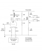
A tube or a mosfet has the same problem in your circuit. You have ~100V across the bottom resistor, if the top resistor is equal, it will also have 100V across it. That leaves the mosfet fully turned on with no way to turn on any further and amplify. This will make a splitter that outputs only half of the AC waveform.
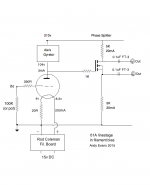
The solution is to either bias the gate at 1/4 HT and couple to the previous stage with a cap or to increase the HT on the concertina stage. For maximum headroom, you would want HT at 400V or so.
A tube or a mosfet has the same problem in your circuit. You have ~100V across the bottom resistor, if the top resistor is equal, it will also have 100V across it. That leaves the mosfet fully turned on with no way to turn on any further and amplify. This will make a splitter that outputs only half of the AC waveform.
The solution is to either bias the gate at 1/4 HT and couple to the previous stage with a cap or to increase the HT on the concertina stage. For maximum headroom, you would want HT at 400V or so.
Something like this? Not keen on two coupling caps...
Yes, or you can eliminate the coupling caps and keep it more like it was by simply increasing the HT to 400V for the concertina stage.
Something like this? Not keen on two coupling caps...
Have you seen a pentode in such splitter? Drain output will be different from source.
Have you seen a pentode in such splitter? Drain output will be different from source.
The screen grid, specifically, is what makes a pentode unsuitable for "concertina" phase splitter duties. Yes, a FET's current/voltage curves resembles those of pentodes. However, with only 3 electrodes, a FET is just fine in the split load phase splitter role. AAMOF, a FET is superior to a triode, in that it can swing closer to the B+ rail.
Have you seen a pentode in such splitter? Drain output will be different from source.
If you give drain and source the same load (which of course, you would), Kirchoff says differently.
For a typical direct coupled input triode to cathodyne arrangement (plate of input triode about 130V, B+ for cathodyne of about 400V) do I need to add any any extra protection (e.g. zeners) if I substitute the current triode cathodyne with a DN2540?
Currently I have a neon from grid to cathode on the cathodyne triode. Hopefully I can just sub in the DN2540 and not blow it up on startup as I only have a couple in my parts box. LTspice says it will work but that is at steady state.
Currently I have a neon from grid to cathode on the cathodyne triode. Hopefully I can just sub in the DN2540 and not blow it up on startup as I only have a couple in my parts box. LTspice says it will work but that is at steady state.
I've been using an LND150 "source-o-dyne" phase splitter in my guitar amp for a year or so.The LND is only rated at 3/4 of a watt in the convenient TO-92 package. Originally I tossed it out of consideration for that reason. But I'm thinking now that even though I'm running 300 volts through that stage I can run well within half that 3/4 watt.
With a 300 V rail, you only want 150 volts across the FET (to allow maximum output signal before clipping.) The LND150 has a minimum guaranteed Idss of only 1 mA. Put those two numbers together, and you'll only have 150 mW of power dissipation in the LND150!
I might add that you can, of course, bias the LND150 positive, and increase Id beyond 1 mA that way, turning the depletion-mode device into an enhancement-mode device in the process. I chose not to do that.
The only remaining piece of the puzzle is choosing the drain and source resistors; with 150 volts divided equally between them, and 1 mA of current, you need 75 k for each one, more or less...
As expected with 100% negative feedback, the LND150 is audibly quite transparent in my application - any distortion it produces is orders of magnitude lower than the distortion from the valves around it, and so cannot be heard.
-Gnobuddy
- Home
- Amplifiers
- Tubes / Valves
- MosFET or other semiconductor substitute for cathodyne?