Hello everybody,
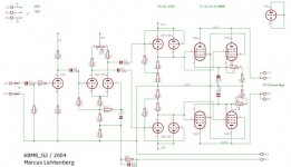
After some triode-amps I have developed a little circuit for a G2-driven amp which should be fine to develop approx. 15W before clipping using 6BM8 or PCL82. And in fact it does with good results - using pspice. Because of these promising results I decided to give it a try in reality and prepare some PCBs for it. But before I start this painful work every comment on the circuit is very welcome (some call it review...).
In general, I prefer circuits with no "over-all-feedback" but I have provided it here fearing some instability. However, dont take the value of the r and c in the feedback-path to serious, the exact values have to be developed in reality")
Marcus
After some triode-amps I have developed a little circuit for a G2-driven amp which should be fine to develop approx. 15W before clipping using 6BM8 or PCL82. And in fact it does with good results - using pspice. Because of these promising results I decided to give it a try in reality and prepare some PCBs for it. But before I start this painful work
every comment on the circuit is very welcome (some call it review...). In general, I prefer circuits with no "over-all-feedback" but I have provided it here fearing some instability. However, dont take the value of the r and c in the feedback-path to serious, the exact values have to be developed in reality
Marcus
Attachments
I haven't tried this with a 6BM8, but I've had great results using G2 drive with sweep tubes. General comments: get rid of o/p stage cathode resistances (except for metering purposes); ground g1 directly, then use a variable voltage at the grids of the cf to set idle current (return the cf cathode resistor to a good negative rail). With sweep tubes, the optimal idle current will be shockingly low (3 ma or so for 6LF6s). I'm not crazy about using a 12AU7 as a cf in this application, but it will still probably work ok.
Sy,
I have chosen the 12AU7 and the 8k-PP Output-Transformer because I have them available.
I trust both, but of course running the 12au7 with significant current. 6LF6s with only 3 mA sounds interesting, less heat, better load-situation for the power supply... have you driven 2 G2 in parallel with them ?
Haven't had to- a single pair with a 1250 ohm p-p load and 600V B+ gives me close to 300 W in short bursts. The grid load of a single 6LF6 driven that way is probably a lot more than the two 6BM8s in parallel.
In a review in Audio some years ago (I think it was for a Berning power amp), Bascom King showed some curves for sweep tubes run this way, low idle current, high B+, cf screen drive. They were impressively linear, triode-like for the first few watts.
In a review in Audio some years ago (I think it was for a Berning power amp), Bascom King showed some curves for sweep tubes run this way, low idle current, high B+, cf screen drive. They were impressively linear, triode-like for the first few watts.
I also like these big sweep tubes, have some 6DQ6 and 6DQ5 waiting for some experiments. However, I never heard a sweep tube amp. But hey, the year has just begun... I will first try these 6BM8s, and than the sweep tube time might come.... For the amp above: I am really considering to use "fixed bias" in the driver stage to set the idle current, its probably better.
Hi SY
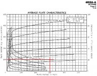
As relaxation therapy between classes, I spent some time looking at Berning's amplifiers (screen driven class B), and, therefore, I tried to do your homework on the 6DQ6 Looking at the curves for G1=0, the curves for G2 seem to meet your requirements:
- evenly spaced,
- not too high a voltage for a reasonable amount of current swing
(Actually they look much like the 6JN6 curves).
But, that's just an indication of suitability, as, if I understood well, the curves for actual operation at very low bias currents are different. (quoting you)
Sure they must be different, as in Berning's amplifiers the screen grids are at negative potential, while, at the curves from the datasheets, they are at positive potential. Also, in Berning's amps the bias current is some wimpy mA, while the curves with positive screen grids show a standing current of several tens of mA. The curves for g1=0 as shown in the curves are actually suitable for a design such as the EL509 by Bob Danielak (I think).
http://www.geocities.com/bobdanielak/technoteNo33.html
As said, I am trying to understand it, for the moment I do not have plans to build something (but, as the driver stage of the CP is in the makes, I may try to use it to drive some 25DQ6B's I have on hand)
Thanks for your attention!
Erik
As relaxation therapy between classes, I spent some time looking at Berning's amplifiers (screen driven class B), and, therefore, I tried to do your homework on the 6DQ6
Looking at the curves for G1=0, the curves for G2 seem to meet your requirements: - evenly spaced,
- not too high a voltage for a reasonable amount of current swing
(Actually they look much like the 6JN6 curves).
But, that's just an indication of suitability, as, if I understood well, the curves for actual operation at very low bias currents are different. (quoting you)
In a review in Audio some years ago (I think it was for a Berning power amp), Bascom King showed some curves for sweep tubes run this way, low idle current, high B+, cf screen drive. They were impressively linear, triode-like for the first few watts.
Sure they must be different, as in Berning's amplifiers the screen grids are at negative potential, while, at the curves from the datasheets, they are at positive potential. Also, in Berning's amps the bias current is some wimpy mA, while the curves with positive screen grids show a standing current of several tens of mA. The curves for g1=0 as shown in the curves are actually suitable for a design such as the EL509 by Bob Danielak (I think).
http://www.geocities.com/bobdanielak/technoteNo33.html
As said, I am trying to understand it, for the moment I do not have plans to build something (but, as the driver stage of the CP is in the makes, I may try to use it to drive some 25DQ6B's I have on hand)
Thanks for your attention!
Erik
Attachments
Tubelab has started doing some work in the direction. He's seeing the same thing I do
I experimented with a screen driven push pull amp that used 6AV5's a while ago. It made 80 watts at clip, and 2.5% distortion at 50 watts with zero feedback. This was an experiment to learn about screen drive. The amp had 3 power supplies hooked up so that I could adjust everything for maximum linearity and power output. I found that I got the best results with a slight negative bias on G1. This allowed a higher swing on G2 for more linear power output. Bias current was low, and the amp was highly efficient, allowing large power outputs without high tube dissipation. The output power was limited only by the maximum voltage from my power supply. Your driver circuit must be capable of supplying a lot of drive voltage and the screen current. I used mosfet followers.
I needed space for some new experiments, so I cleaned this design off of my breadboard just last weekend. At least this time I documented the design. I could post the schematic this weekend if anyone is interested.
Attachments
wfmali said:developed a little circuit for a G2-driven amp
Can you post a slightly larger gif (or vector pdf) of the schema... the jpg noise in the one you did post makes it hard to suss the details.
dave
can you post a slightly larger gif (or vector pdf) of the schema...
Dave,
looked for the file(s), but apparently did not save anything of that idea over the years - sorry! It never really made it beyond pspice, although I remember that I started to design a pcb with eagle. I still like the idea, it's definetly something worth a reheat.
I played with larger tubes G2-driven that year - with EL509IIs in PP driven by 6BX7s. This amplifier actually made it on the bench - but not further - could not get the ELs to balanced bias, which of course was a big problem for the torrodial opts that I used (They are serving happily in a rather conventional 4*EL34 PP triode strapped configuration now...)
Marcus
tubelab.com said:
I experimented with a screen driven push pull amp that used 6AV5's a while ago. It made 80 watts at clip, and 2.5% distortion at 50 watts with zero feedback. This was an experiment to learn about screen drive. The amp had 3 power supplies hooked up so that I could adjust everything for maximum linearity and power output. I found that I got the best results with a slight negative bias on G1. This allowed a higher swing on G2 for more linear power output. Bias current was low, and the amp was highly efficient, allowing large power outputs without high tube dissipation. The output power was limited only by the maximum voltage from my power supply. Your driver circuit must be capable of supplying a lot of drive voltage and the screen current. I used mosfet followers.
I needed space for some new experiments, so I cleaned this design off of my breadboard just last weekend. At least this time I documented the design. I could post the schematic this weekend if anyone is interested.
Sorry to crash in here slightly off topic, but where did you get that clever breadboard setup? Did you build it?
I'd like to make something like that for experimenting.
Marc
Sorry to crash in here slightly off topic, but where did you get that clever breadboard setup? Did you build it?
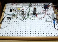
Yes, I built it. I have made several solderless breadboards over the last few years. This is the first one that I have actually used for multiple designs. The base is made of wood with grounded copper screen stapled to it. Next I mounted a piece of Nylon pegboard about 1/4 inch above the screen with screws. The pegboard came from Lowes home improvement warehouse. Then I made several modules for each of the popular tubes, and a few universal modules. They are simply a tube socket mounted to a small piece of pegboard with "Euro style" barrier strips connected to the tube socket. The dedicated modules have grid stopper resistors already on them. The universal modules simply have a tube socket and barrier strips. I placed 1/4-20 bolts (held by nuts on the back) at each corner so that the module will stay in place. I also made modules with only barrier strips for mounting discrete components.
There are a few more details here. I have more pictures, I just haven't had the time to post them yet.
http://www.tubelab.com/The_Tubelab.htm
I will post the schematic as soon as I photograph it and process the picture. (tonight or tomorrow)
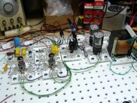
Here is a simpleSE amp undergoing testing. It is being used for several experiments.
Attachments
Nylon pegboard.... never crossed my mind.
I had never heard of it. I went to Lowes for some stainless steel nuts and bolts. It was there staring at me saying, "go ahead build something." I bought a piece not knowing what I was going to build yet. It sat next to my bench for a few months until the idea hit. Then it was a matter of hours until I had the breadboard. I have made some leads with aligator clips on them for trying out a lot of parts in a short amount of time. I will post some more pictures on the web page as soon as I can process them.
That is clever! I think I'll copy the idea if you don't mind?
That is why I put it on the web site.
This is the stuff I used, however the Lowes search engine can not find it even if I give it their stock number.
http://www.geomatrix.info/PegMaster/faq.html
http://www.geomatrix.info/PegMaster/faq.html
- Status
- This old topic is closed. If you want to reopen this topic, contact a moderator using the "Report Post" button.
- Home
- Amplifiers
- Tubes / Valves
- G2-driven 6BM8