I would like to see the schematic with the 6AV5!
OK, at least it isn't as far OT.
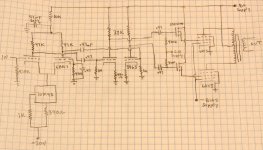
I had adjustable power supplies hooked up when designing this amp. Main B+ was tested up to 555 volts, the limit of my power supply. The SG supply was adjustable up to 400 volts, the 6AV5 worked best at about 325 volts. This is just a bias voltage for the fets (no current) so it could be done with a pot. Same thing with the G1 bias voltage. The 10M45 CCS IC needs some negative voltage to work. An LM334 will work with far less voltage.
Use what you want from this schematic, but there are no guarantees. I will get back to this design someday.
Attachments
Hi George
Being the thread about screen grid drive, and as we have a working example from you, I thing it's not OT.
Thanks for the schematic. So, just to confirm, the screen grid's are biased through a positive supply? This is, I believe, contrary to the biasing of the sweep tubes in Berning's amplifiers, where, if I calculated well, bias on the screen grid's is negative. How much current was there through the 6AV5's, at idle?
Erik
The screen grid should be positive. 6AV5's require a large voltage swing on the screen grid. Mine were swinging from nearly zero to nearly 500 volts. Many people say that G1 should be grounded, but I got the best results with a slight negative voltage. This allowed me to hit the screen grid harder for more power output.
I played around with the idle current a lot. It is a function of both the screen grid voltage and the G1 voltage. I made both adjustable in this design. I found that for these particular tubes the best compromise between linearity and power output was at about 12 mA total (6 per tube). If you decide to build a screen driven amplifier make both grids adjustable and tweak for best results. I was watching the FFT analyzer and trying to balance between minimum harmonics at low power and lowest distortion at full crank. This may be different with a different pair of 6AV5's since there are at least 6 different types of 6AV5's that I have. A different tube would need some tweaking.
I played around with the idle current a lot. It is a function of both the screen grid voltage and the G1 voltage. I made both adjustable in this design. I found that for these particular tubes the best compromise between linearity and power output was at about 12 mA total (6 per tube). If you decide to build a screen driven amplifier make both grids adjustable and tweak for best results. I was watching the FFT analyzer and trying to balance between minimum harmonics at low power and lowest distortion at full crank. This may be different with a different pair of 6AV5's since there are at least 6 different types of 6AV5's that I have. A different tube would need some tweaking.
Hi George and others
Yes, the curves really show that VG2 should be positive, but I looked again and agais at Berning's schematics, and I can't see how the screen grids would be at positive potential in his designs. I even cut the output stage, and pasted the calculated values of voltage at the grids of the cathode follower outputs, and the expected voltage at the screen grids. This is on the assumption that the 6SN7's will have their cathodes slightly higher than the grids (which is were negative bias is applied). The 6SN7's seem to be biased in class B to, but, if that matters much...
I would be very thankful for your insight
The schematic is a cut from the output stage of the EA 2100, whose full schematic can be seen as david berning's site/
Erik
Attachments
Looking at the Berning schematic I suspect the negative values cited are probably the voltage present at idle. I would assume from the +360V on the plates of the 6SN7 CFs that large positive voltage excursions are possible and likely in normal operation on the output tube screens - also I think biased fairly close to pure class B territory..
Bear in mind that the effective mu of a screen driven tetrode is quite low. (This topology has also been referred to as enhanced triode operation in some quarters. Tim DiParavicini designed an SE amp project around this idea more than a decade or so ago.)
George's design is likely to extract a little more power out with better linearity for a given tube type, but at the expense of additional setup complexity.
Looking at the Berning schematic I suspect the negative values cited are probably the voltage present at idle. I would assume from the +360V on the plates of the 6SN7 CFs that large positive voltage excursions are possible and likely in normal operation on the output tube screens - also I think biased fairly close to pure class B territory..
100% correct. About 3mA idle current, and just a few volts negative bias on the screen (control grid connected to the cathode). The CF needs to swing at least 150V positive. Note that in reality, the CF is also close to class B. Given the large swings, it's no wonder I've preferred using FETs there.
The CF needs to swing at least 150V positive.
Given that the voltage on screen grid swings so much (from slightly negative to about 150V) isn't the use of -145V for the negative rail somewhat to low a value? Increasing it would not be hard!?
This is fascinating!
Any thoughts on whether either a 6JB6 or 6146B would work in this arrangement (in terms of voltage swings, bias and such)? I've got a number of both of those... as in about a DOZEN 6JB6s and 8 6146Bs!
Think of parallel push pull 6JBl6s... in theory, AFAIK, it could be three times as powerful as a single pair of 6AV5s, if you go by comparison of plate dissipation! If you're gonna go, GO BIG!
Regards,
Gordon.
If you're gonna go, GO BIG!
Then I have to try some parallel 6LW6's. If I only had a suitable OPT. I have stashed away about 20 of the various 'LW6 tubes over the past 10 years. They are just about the biggest sweep tube that I know of. Closely related to the 6LF6 (different base). They used to be cheap, not anymore.
The 6JB6 should work just fine. I think that the 6146 may require a lot of drive voltage, but only some testing will tell for sure. I have plenty of both tubes, but I don't know when I will have the time to experiment.
I have been working on a "universal PowerDrive" circuit that should make driving these things easy. I will put the circuit on my web page when the testing is done.
Nice tubes! Screen drive should work, but the curves you really need to determine this aren't on the Philips datasheet. But squinting at what's there, it looks like you can pull nearly an amp with Vgk = 0 and Vg2 =300V. So it will take some swing to do it, but it can be done.
The lack of curves with Vgk = 0 and the Vg2 as the variable makes judging linearity in this mode difficult. But if I had a quad of them, I'd very much want to find out...
The lack of curves with Vgk = 0 and the Vg2 as the variable makes judging linearity in this mode difficult. But if I had a quad of them, I'd very much want to find out...
It appears that the output impedance of screen grid drive mode is the same as pentode mode, ie. Hi-Z, since the plate is still shielded by g1 and g2. So I am assuming one needs feedback of some kind here to lower the output Z.
Has anyone plotted current gain (Ip/Ig2) versus output current for this mode?
Don
Has anyone plotted current gain (Ip/Ig2) versus output current for this mode?
Don
- Status
- This old topic is closed. If you want to reopen this topic, contact a moderator using the "Report Post" button.
- Home
- Amplifiers
- Tubes / Valves
- G2-driven 6BM8