Many thanks Bas and Adolf, your advice here is greatly appreciated. This certainly gives me something to go off.
What type of resistor is it best to replace this with if needed as I am not entirely sure? Is it a wirewound?
My room is asymmetrical plus my right ear is a touch down compared to the left so I had often put down the imbalance to those factors (or turntable setup). The imbalance had grown a little recently but after the capacitor and pot mods it is huge.
I'm not quite sure, but those original resistors look like a 2W metal oxide type. Though I think even a 1W resistor should be quite sufficient here. Maybe swap both of them for metal films if you can't get the exact original type? Should be inaudible though, but for peace of mind...
Still, check first if it's the cap or the resistor that's gone. I don't remember seeing resistors shorting... They can go up in smoke and flames, though, rather spectacularly when you fudge something up bad enough. Leaving behind a really fragrant ghost. Man, my lab smelled after that...
Still, check first if it's the cap or the resistor that's gone. I don't remember seeing resistors shorting... They can go up in smoke and flames, though, rather spectacularly when you fudge something up bad enough. Leaving behind a really fragrant ghost. Man, my lab smelled after that...
Hi chaps, thanks again so much for taking the time to offer me advice.
So I removed the 1.5K reistor and the tiny 330pf cap and alas they both test fine. I could not get a read from the resistor in circuit whereas I could from its opposite partner.
Would you advise removing the various caps and testing these? All of the caps are new except the 470uf pair of cathode bypass and the 0.47uf coupling caps. Is it better to test with the amp live to see if they are leaking DC?
Many thanks.
I expected as much. But it was worth a try.So I removed the 1.5K reistor and the tiny 330pf cap and alas they both test fine.
What I would do is measure the b+ on all anodes for both channels.
Measure the voltage accross all cathode and/or plate resistors. Measure -C the bias for the output tube.
Thanks again guys. I will check those. I have tested every resistor in and around the tubes while in circuit and they all checked out (apartg from that one). I guess I will need to remove the caps to check those.
I can only guess that I didn't "probe" in the right place or my probes were not conducting at those points perhaps. I did try for quite a while before removing the components.
I have not done any testing on this amp before when powered up. Aside from the usual safety precautions. Am I correct that I will need to ensure either a dummy load or a speaker is connected to prevent any issues with amplifier?
If the schematic is correct, there's no internal load at the secondary, so yes, you should use a dummy. Anything from 8 ohms to 100 ohms on the 8 ohm output tap should do the trick.
The point is only that the secondary should not be unloaded at any point when the unit is powered, since a small spike on the primary could develop a very large voltage on the unloaded secondary.
The point is only that the secondary should not be unloaded at any point when the unit is powered, since a small spike on the primary could develop a very large voltage on the unloaded secondary.
Thanks again for your help.
Before going further I have double checked my pot again by running a mono signal into the RCA input and measuring the AC voltage coming from the pot into the first valve and I am getting the same voltage at various volume settings.
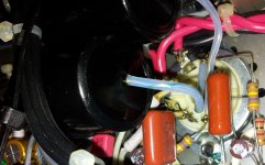
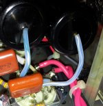
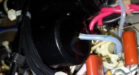
I just noticed actually that there might be something leaking from the Mundorf Silver Oil 0.47 coupling caps that I fitted a few years ago but I am unsure, it is like a blue liquid coming from the lead outs and down the teflon tubing that the leads are run through to the tube sockets. I have attached a couple of images as I have not seen this before and do not know if this is an a real issue or not?
I did find a post on this forum complaining about the long term use of Mundorf SIO caps in hot amplifiers. The Almarro is known for becoming extremely hot both internally and externally to the point where the volume knob gets quite hot to the touch.
Before going further I have double checked my pot again by running a mono signal into the RCA input and measuring the AC voltage coming from the pot into the first valve and I am getting the same voltage at various volume settings.
I just noticed actually that there might be something leaking from the Mundorf Silver Oil 0.47 coupling caps that I fitted a few years ago but I am unsure, it is like a blue liquid coming from the lead outs and down the teflon tubing that the leads are run through to the tube sockets. I have attached a couple of images as I have not seen this before and do not know if this is an a real issue or not?
I did find a post on this forum complaining about the long term use of Mundorf SIO caps in hot amplifiers. The Almarro is known for becoming extremely hot both internally and externally to the point where the volume knob gets quite hot to the touch.
Attachments
Thank you for looking at those images.
This one of the 0.47 coupling caps between the first stage (V1) 6Sn7 and second stage (V2) 6SL7.
I had just taken it out when this post arrived. It tests on the capacitance meter but I appreciate that this is only part of the story.
Is there a quicker way to check for DC leakage than putting this cap back into the amp and I would also need to replace the 1.5k resistors and small 330pf caps I had removed. I struggled to reach these and clipped them rather than attempting to desolder. It will be tricky to get them back in. I have new replacements coming in the post. EDIT - I guess I need a high voltage DC source to really get an idea of leakage?
Last edited:
Well, yeah, basically the easiest way would be to check that there's no DC after the cap with the amp running. V2 grid is referenced to ground via its grid resistor, so should show 0.000VDC with no signal.
Still, this does not explain why you couldn't get a reading over the 1,5k feedback resistor when it was in circuit. It should show approximately the value of the parallel connection of the 22 ohm cathode resistor and the 1,5k feedback resistor when it's connected (they're parallel because the secondary winding shorts the other end of the 1,5k to ground). So it should look like (1500 x 22)/(1500 + 22) = ~21,7 ohms.
Still, this does not explain why you couldn't get a reading over the 1,5k feedback resistor when it was in circuit. It should show approximately the value of the parallel connection of the 22 ohm cathode resistor and the 1,5k feedback resistor when it's connected (they're parallel because the secondary winding shorts the other end of the 1,5k to ground). So it should look like (1500 x 22)/(1500 + 22) = ~21,7 ohms.
Thank you.
Hopefully I will get the parts tomorrow and I can try this along with the other tests that have been advised in this thread. I have some 8ohm 50watt panel mount resistors coming to use as a dummy load also.
As for the lack of a reading when measuring across the 1.5k resistor when it was in circuit, I have just put that down to the test probes not getting a good connection since the resistor tested fine once it was cut out of the circuit. I guess there can't be any other good reason for this. I could get a reading of course from its partner on the other channel so assumed I had found the issue.
I took resistance readings across each resistor separately in circuit and got the values shown on the schematic except for the troublesome 1.5k that wouldn't read.
If those parts seem to be okay, you can just solder them back in the circuit. But do make sure there are no other possible short circuits around there before you do so.
A leaking cap of course could be the reason. The next thing to do is to turn the amp on and measure all the voltages around the tubes and ensure they're about equal between channels. 8dB difference between channels is a bunch, so you should find something obvious enough. All anode voltages, grid voltages, cathode voltages... Those should be enough for starters.
And really, for testing purposes, since you're not going to have anything at the output (input shorted/volume pot at zero) just a 2W 100 ohm resistor at the loudspeaker terminals is all you need for a dummy load. When you start testing at full power, well then you'll need a more sturdy load.
Hello,
Thanks again for your advice.
I decided to remove the Mundorfs that look like they are leaking. I put the original caps back in and put the new 1.5k resistors and 330pf caps in.
I turned on the amp and tested the voltages at all the tube sockets.
On the first input tube the 6SL7 I got 68v and 65v on the plates with 3v and 3v on the cathodes.
On the second input tube the 6SN7 I got 382V and 384V on the plates with 4v and 4v on the cathodes.
On the 6c33c output tubes however, I had 312v on both plates, roughly 65 volts on both cathodes (the bias was drifting a little) but at the grid -70v on one output 6C33c and the side with the issue the grid was down at -41v on the grid.
This must surely be causing the channel imbalance? I am really struggling with how to trace the reason for this.
Sorry, I realise now that it is purely the independent bias setting that is influencing this at reading at the grid of the output tubes.
So the only discrepancy is the 3 volt difference between the plates
on the first input tube the 6SL7 where I got 68v and 65v. I guess this isn't anything that would cause a large channel imbalance.
So the only discrepancy is the 3 volt difference between the plates
on the first input tube the 6SL7 where I got 68v and 65v. I guess this isn't anything that would cause a large channel imbalance.
Correct. That is as good as it gets so to speak.I guess this isn't anything that would cause a large channel imbalance.
Thank you for that confirmation.
So at present I have changed the possibly leaky caps, plus the 1.5k resistors small 330pf caps on the first input valve and while I was there I also changed the 470uf cathode bypass caps on the first input valve.
Since I have changed several variables there I will try the amplfier in my system again tonight and cross my fingers!
Am I correct that the next logical step would be to check (as has been kindly advised in this thread) the voltages across the cathode resistors of all the tubes?
I just checked the readings I wrote down late last night and the cathode voltages on the output tubes were actually 64v on the bad side and 70v on the good side. I had put "roughly 65v" in my previous post.
Is this 5v difference at the output tube cathode anything to be concerned about or is this just a variable depending on the negative bias set by the bias trimpots for each output tube? Apologies for my confusion here!
Many thanks again in advance.
You've done that already haven't you?Am I correct that the next logical step would be to check (as has been kindly advised in this thread) the voltages across the cathode resistors of all the tubes?
64/70 is not all that bad either. Have you swapped the output tubes before as a test? The left one in the right channnel...and vice versa. (I know you have changed all the tubes before as you said earlier...) but just to be sure...I was wondering if you have tried that.
Hi Bas and thank you again for casting your eye over my readings.
Yes I swapped the output tubes over prior to exchanging them for a different pair. When I plug in tonight in the system with fingers crossed, I will be sure to try this again to rule out any tube issues, I have a third older pair I can try.
I know I should have tested the leaky caps but I decided to just get rid for now.
I only tested voltages at the valve socket pins. I have not yet tested voltages across the cathode resistors, or are you saying that this is not necessary since the voltages at the valve base pins are correct?
If you tested the valve pins for the cathode. You have effectively measured the voltage across the cathode resistors. As the cathode resistors are at ground potential on the one side.. I have not yet tested voltages across the cathode resistors, or are you saying that this is not necessary since the voltages at the valve base pins are correct?
- Status
- This old topic is closed. If you want to reopen this topic, contact a moderator using the "Report Post" button.
- Home
- Amplifiers
- Tubes / Valves
- Almarro A318B SET Amplifier Simple Modifications For Improved Performance?