Hello folks,
I need to make a couple of simple repairs to my Almarro A318B SET integrated valve amp ([FONT=Courier New,Courier,Monaco]2x6C33C, 1x6SL7, 1x6SN7)[/FONT]. Namely changing the selector switch which is intermittently causing issues plus the IEC socket which has a crack in the plastic casing.
While I am in there I wondered about the potential for any simple upgrades by swapping like for like components. A few years ago I swapped the coupling caps and this was a huge step up in performance.
I have already changed the input valves after tube rolling with a small selection of valves.
Is there anything else that could be achieved with a simple swapping of components for better quality ones. The power supply caps perhaps? Could these be uprated by 10% or am I risking damage here and playing with fire? Would swapping for better quality caps at the same rating be worthwhile?
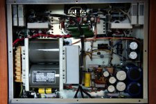
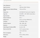
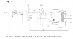
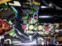
I have attached two images of the amp plus the specs and the schematic which is included in the manual (input and output). Unfortunately I cannot find a schematic for the PSU.
Many thanks in advance.
I need to make a couple of simple repairs to my Almarro A318B SET integrated valve amp ([FONT=Courier New,Courier,Monaco]2x6C33C, 1x6SL7, 1x6SN7)[/FONT]. Namely changing the selector switch which is intermittently causing issues plus the IEC socket which has a crack in the plastic casing.
While I am in there I wondered about the potential for any simple upgrades by swapping like for like components. A few years ago I swapped the coupling caps and this was a huge step up in performance.
I have already changed the input valves after tube rolling with a small selection of valves.
Is there anything else that could be achieved with a simple swapping of components for better quality ones. The power supply caps perhaps? Could these be uprated by 10% or am I risking damage here and playing with fire? Would swapping for better quality caps at the same rating be worthwhile?
I have attached two images of the amp plus the specs and the schematic which is included in the manual (input and output). Unfortunately I cannot find a schematic for the PSU.
Many thanks in advance.
Attachments
Frequently found SS diodes are 1N4007 (1 A.) and 1N5408 (3 A.). They generate quite a bit of switching noise. The corresponding UFnnnn parts are drop in replacements that are much quieter.
An inexpensive Lorlin switch ( 2 - 6 selectable positions) will dispose of the source selection problem.
I intensely dislike IEC connectors, as they are just another mechanical connection that causes problems. Replace the trouble maker with a "captive" 3 wire, safety grounded, power cord. Mount clamp a ferrite on the new power cord close to where it enters the chassis. Don't forget strain relief.
Last edited:
It is always tempting to do that. In the end I don't think it is worth it.Would swapping for better quality caps at the same rating be worthwhile?
As you've discovered....upgrading coupling caps can be very worthwhile though.
What type/brand capacitor is doing the output stage bypass (160v/100uF) duties? This is a cap that can make a difference.
Thanks for the advice. I will have alook into that cap when I get home. Looking back at the picture for the time being I would say it looks like a bog standard electrolytic cap. Would this be a good candidate for an Os-con?
I am looking at replacing the Mundorf silver oil 0.47 I put in with some Jupiter copper foil paper & wax. I might do the previously untouched 0.22 and also replace with Jupiter.
this amp produces alot of heat even by valve amp standards. Should I be coincerned about putting the Jupiters into that kind of environment?
Many thanks!
That depends. The 6c33c generates a lot of heat. But does your amp get warm under the chassis as well? By the way the current generation of jupiters are a whole lot better whenShould I be coincerned about putting the Jupiters into that kind of environment?
it comes to heat compared to the earlier models.
If they are available in 160v/100uf sure. They have a good reputation.Would this be a good candidate for an Os-con?
But be warned...the boutique cap game is one of diminishing returns.
") I.e. very little bang for the buck...except in my opinion when it comes to coupling caps. But as long as you have fun and the family is fed...
I.e. very little bang for the buck...except in my opinion when it comes to coupling caps. But as long as you have fun and the family is fed...You might like a combination of the two. I also like jupiters...but they are so neutral and have no edginess...sometimes too much of a good thing might cause your amp to sound tamer...all depending on your tastes and other equipment ofcourse...I am looking at replacing the Mundorf silver oil 0.47 I put in with some Jupiter copper foil paper & wax
Thanks again for the advice it is much appreciated.
Yes when I put in the Mundorf the mid range got a big boost, it was actually a bit much at first but exciting at the same time. It was like the amplifier had been given a shot in the arm. It settled down slowly after that.
The Os-con caps unfortunately don't go up to 160V. Do you have any suggestions for some nice caps to use for the output stage bypass (160v/100uF)?
I am also looking at a 24 step potentiometer, shunt design to replace the 250K standard pot that is in there already. Do you think that there would be any disadvantage coming down to a 100k pot? The 250K standard does seem quite high.
I am now a little confused at the moment about the effect of the input impedance relative to the volume control position. I had thought (incorrectly?) that this was kept constant, being the series plus the shunt resistance = the input impedance, forgetting for a moment the source that the pot is driving. Or is the input impedance just the shunt leg value?
Thanks again
No..that is fine.Do you think that there would be any disadvantage coming down to a 100k pot?
Not too clued up on the cap that is in vogue these days. Black Gates used to be very popular..but unobtainium thesedays. I usually go for film caps...but space is a problem in your amp.Do you have any suggestions for some nice caps to use for the output stage bypass (160v/100uF)?
Hello and thank you for your reply.
I got inside the amp to check out the available space more clearly and found that there are two small caps that appear to be on the output of the alps 250k pot. What would likely be the function of these? DC Blocking caps? If this was the case surely I could consider leaving these out when I fit the new stepped pot. They do not appear on the schematic.
I might be able to squeeze 100uf polypropylenes for the output tube bypass caps but would need to extend the leads 2-3 times their current length to access room to fit these. Is there any reason why this would be a bad idea?
Many thanks again!
Yes.What would likely be the function of these? DC Blocking caps?
Yes.If this was the case surely I could consider leaving these out when I fit the new stepped pot
You could also try 3 * 33uF paralled if that would be easier to fit. The long leads are in my opinion not a problem.I might be able to squeeze 100uf polypropylenes for the output tube bypass caps but would need to extend the leads 2-3 times their current length to access room to fit these
Hello,
Thank you again for taking the time to reply!
I got inside the Almarro A318B yesterday and completed the following work :
- Channel Selector Switch
replaced
- 250K Volume pot replaced with 100K stepped shunt pot
- IEC socket removed and captive power cable installed
- 0.22uf coupling caps replaced with Jupiter Copper Foil Paper & Wax Caps.
- 100UF 160v Electrolytic Cathode bypass Caps on 6c33c output tubes replaced with 100UF Jantzen Cross Polyprop film caps.
- 100UF 16v Electrolytic Cathode bypass Caps on 6SL7 input tube replaced with 100UF OSC-Con SEPC polymer caps.
To fit in the large 100UF Jantzen polyprop caps in place of the electrolytics on the output tubes I had to extend the wire from the valve pins, I also had to move the two parallel 0.1ohm 15 watt resistors that were across the output tubes so that these could be placed elsewhere in the amp to make room.
I finished quite late and only had a brief chance to switch on the amp due to work commitments today but I had quite a large channel imbalance. I checked the volume pot wiring and all seemed well there.
Is there anything about the above work that would cause this asside from an error in the soldering work?
I do have suspicions about one of the output tubes and also one of the 6SN7 input tubes and will check these when I am home again. One of the output tubes was running way over the recommended bias voltage when I powered up and checked this. The 6SN7 has become increasingly noisy over the last few weeks upon switch on and the noise goes when I put an old 6SN7 back in that it replaced. It does however seem a bit of a coincidence that one of the valves would fail and cause an imbalance just after I completed this work.
Many thanks in advance any input would be greatly and humbly appreciated!
Last edited:
I would still suspect the volume pot and/or wiring of it.I had quite a large channel imbalance. I checked the volume pot wiring and all seemed well there.
A bypass cap not properly connected on one channel could be the culprit as well.
But if the volume imbalance changes as you turn the volume knob...that would be wiring of the volume control.
Thank you again for your reply.
I will check the coupling cap wiring and the pot again also.
I did measure the resistance on both RCA inputs from signal to ground and observed the same resistance at each step of the pot. I guess I need to still check the wiring but that was a test I could do easily without opening the amp up and I was expecting to see a mismatch between channels.
as a side issue, I noticed when wiring the captive mains lead and removing the IEC socket that the internal fuse is on the neutral line and not the hot power line. What would be the reason for doing it this way? I checked some images on line of my amplifier and they also appear to have the hot pwer line unfused but have a fuse on the neutral.
Sounds like a mistake.I noticed when wiring the captive mains lead and removing the IEC socket that the internal fuse is on the neutral line and not the hot power line. What would be the reason for doing it this way?
Hello Bas,
Thank you again.
I changed all of the valves last night and I am still getting a significant imbalance. I measured this at the listening position to be sure and saw a drop of roughly 8db. I had the pre mod measurements to compare to also.
I have noticed that over the last year my system does have a bias towards the left side which I have battled with often using speaker placement. it is now however much more significant and unworkable.
It also noticeable that there has always been a very feint transformer hum on the speaker that is connected to the louder channel, the quieter channel has never had this feint transformer hum but has always been a little more noisy.
- Anyhow, perhaps these are red herrings. I got inside the amp and checked the pot, at all steps I am getting the correct series and series to ground resistance and checked these against the attenuator calculator which showed the values to be within 1db of each other.
- I got inside the amp to check my soldering and various connections, everything appears to be correct as I compare the "bad" channel to the "good" channel.
- I then thought to check the resistor values against each other channel to channel around the input and output tube sockets and everything checked out apart from one resistor which I cannot seem to get a reading on at all with my multimeter probes. This 1.5k resistor is close to the 6SL7 (6H9C) first stage input valve and does not appear to be shown on the basic channel schematic. The 1.5k resistor opposite tests fine but I either get strange low reading or no reading at all across the reisistor with the arrow in my attached image (schematic also attached again).
If you could pass any comment on this particular element that I have identified that would be greatly appreciated!
I intend to obtain a meter to check all of the capacitors as my meter cannot check these with its test probes. I guess that if one of the caps is leaking DC however the only way would be for the amp to be powered up while testing which of course is a whole other thing to consider.
Many, many thanks again in advance.
Attachments

Looks like that is the 3k cathode resistor on the schematic. Probably went to 1.5k for a better operating point.
They should obviously both read 1.5k +- 5% or so. You could also try to measure the voltage across the left and right cathode resistor (1k5)
I suspect the cathode resistor bypass cap could be bust (unlikely because of the low voltages there..but more likely than the resistor not being ok anymore).....maybe heat did it in....so try to solder it out and measure again.
That could well be your problem. (Which was perhaps masked by an imbalanced potentiometer).The 1.5k resistor opposite tests fine but I either get strange low reading or no reading at all across the reisistor with the arrow in my attached image
They should obviously both read 1.5k +- 5% or so. You could also try to measure the voltage across the left and right cathode resistor (1k5)
I suspect the cathode resistor bypass cap could be bust (unlikely because of the low voltages there..but more likely than the resistor not being ok anymore).....maybe heat did it in....so try to solder it out and measure again.
Last edited:
I think that 1.5k resistor is your feedback resistor. Now, that would definitely skew your balance if it were shorted! That Wima cap that is in parallel is the feedback compensation cap. It's a polyprop, which usually fail open, but you could solder it off to check if it's the cap or the resistor that's shorted.
O...yes you are correct!I think that 1.5k resistor is your feedback resistor
- Status
- This old topic is closed. If you want to reopen this topic, contact a moderator using the "Report Post" button.
- Home
- Amplifiers
- Tubes / Valves
- Almarro A318B SET Amplifier Simple Modifications For Improved Performance?