Actually the outputs feed a simple OP amp based summing circuit which feeds a DSPeaker room correction device - that feeds the sub. The leads to the sumer are DIY with a capacitance of ~3.5pF/foot.I suspect you need the sub input fairly close to the transformer, as they don't like capacitive loads?
Interesting to compare your amp to my fat boy, especially the FFTs. Your differential input stage definitely achieves lower distortion, though I sorta wanted a little H2, which the SE input provides.
I can't believe I'm actually asking this, but what do you think of the way it sounds?
To my ears, the fat boy amp sounds better than anything else I've designed. So much so that I'm at a loss as to what to do next...
As an engineer, I'm not quite able to explain why it sounds so good. I have some theories but nothing concrete. That certainly bothers me ��
Pete
Hi zigzagflux,
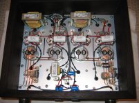
I will let more experienced people here with more sophisticated test equipment comment on your measurements... But I'd like to say that your layout and build is very impressive, especially how you stacked those filament supply modules (?) before reaching the Coleman reg boards..
If ever you plan to rebuild again maybe you could consider another DHT like the 10Y for the CCS plate load -> cap coupled LTP input stage.. I'm not sure though how you would compensate for the lower mu of the DHT. Maybe wire an input phase splitting iron with step up gain? Or maybe you could score a quad of relatively matched 841 higher mu DHT's..
It would be great if you can post the PSU schematic. And please do update us on the better matched 46's or if ever you decide to switch to 45's...
I can't believe I'm actually asking this, but what do you think of the way it sounds?
To my ears, the fat boy amp sounds better than anything else I've designed. So much so that I'm at a loss as to what to do next...
Still in the 'garage' stage, testing and running it through a few hours of beatings before putting them to my valuable speakers. I can say that the first version was one of my favorite amps, even though it had some significant shortcomings. Depending on my mood, I would enjoy my SET amp as well. I certainly look forward to the audition, possibly this weekend.
Having all the filament regulators mounted to the top plate, in addition to the cathode resistor, puts out a lot of heat that must be dealt with. The plate runs around 53C in a garage where ambient is currently around 38C. Hot to the touch, for sure, but just tolerable. I also note that the 'lytics in the filament power supplies get pretty warm, but I always make certain to buy 105C caps for good reliability. Heat is not your friend, so just taking the time to really make sure I have a reliable design. I may have to reconsider putting this baby on carpet; will probably have a little plywood platform for each mono block to sit on.
But I'd like to say that your layout and build is very impressive, especially how you stacked those filament supply modules (?) before reaching the Coleman reg boards..
It would be great if you can post the PSU schematic. And please do update us on the better matched 46's or if ever you decide to switch to 45's...
Thank you for the kind words. I admire the mechanical wonders of Thomas Mayer - VinylSavor
He was the inspiration to maximize the use of space, which also helps localize the nasty magnetic strays caused by the rectifier transformers. I have had other designs that were a disaster, especially when using 60 Hz chokes.
As much as I would love to run 45's, it just ain't gonna happen. I'm certainly not a penny-pincher, as I believe is attested by the pictures, but to spend $35-$85 for used/new tubes, and then struggle to find matched pairs, was a little out of control for me. A set of 300B's is not exactly pocket change, either. I tried to compromise the SN7 route by buying a big batch of the less popular 12SN7 (most not A or B) and hand selecting. Great way to get superb triodes.
Power supply attached. All shielded transformers and separate split bobbin Hammonds for the heaters of the damper diodes. Chokes are Hammond. Snubbers selected based on actual scope waveforms. Nothing special, really.
Attachments
IMD loopback and result. Would this be interpreted as an 0.56% result? Seems a little high, but then again it isn't a feedback design. Would it be proper to assume that one would get significant amounts of 1 kHz, 2 kHz, but ideally very little above that, whereas a high feedback design might have very low but detectable higher order products, such at 7 kHz, 9 kHz?
Attachments
Very cool your amplifier construction, congratulations!! And great THD results! I can imagine this sounds very good.
A little about perfecting yet more the FFT readings: to make better use of the measuring range, it is best to use an adjustable input attenuator (a pot, for example) and try to use the sound card always with a signal near 0dB. So you can go "over the background" and find more "hidden" harmonics. With a -20dB for example we are already losing a few bits of resolution. Check before in loopback if not appear undesirable harmonics with the most "near 0dB" signal.
Of course, some FFT programs shows "off mark" scale and the real 0dB "saturation" input maybe can -10dB or sometimes +10dB (like in an old Spectralab version I have worked some years ago). Is better to check this first.
For my measurements I use a Asus Xonar (to Arta FFT) with a input pot (and buffers only for high impedance signals) and I always try to perform the measurement between -10 dB and zero dB adjusting the input. The "real" 0dB are +1dB in graph but Arta permits calibrating.
Last edited:
Nice time travel machine
Those people dont know what they talking about. it is like fried meat without spices -H3, and salt -H2 tastes so true, so real meaty..
Even so much truthfully, it will make you puke. Tried it, very disgusting sod that.
And there is speaker distortion, way bigger than amplifiers alone(don´t tell them)
It is the same issue I faced 17yrs ago with my first SE amp designs, the fact that I no longer build PP amps for my own use says it all. Of course I obviously like effect boxes or so I will be told.. lol
Those people dont know what they talking about.
it is like fried meat without spices -H3, and salt -H2 tastes so true, so real meaty..Even so much truthfully, it will make you puke. Tried it, very disgusting sod that.
And there is speaker distortion, way bigger than amplifiers alone(don´t tell them)
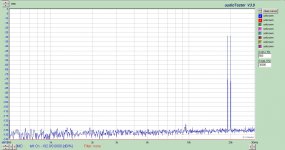
Performance at 1W into 4 ohm resistive load. The captions near the top of the image explains the conditions.
First is the speaker output. 0.02%. Note the sidebands around the fundamental are 120 Hz, which originates from the 250mV ripple present on the output stage B+. The input and driver stage have no ripple effect, as the input stage benefits from the CCS rejection, and the driver stage is shunt regulated with gas tubes.
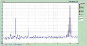
Next is the same conditions, but measurement is differential at the grids of the 46 triodes. This shows the input stage is doing a very fine job at 0.011%. Depending on the tube I use, I can improve the input stage performance. I have a few stellar SN7's that have been verified, and will use those when actually listening to the system. But for testing purposes I picked a good (not stellar) one.
Finally is the differential measurement at the grids of the 300B's. A little additional distortion has been added in the driver stage, but very minimal. I may experiment with matching pairs based on FFT and bias to try and improve the driver, but generally the triode connected 46 does a fine job.
Splendid design work, and very useful characterising measurements. Thanks for sharing!
Lower open-loop distortion of 300Bs is particularly notable with a reactive load (ie loudspeaker) and frequency sweep is applied. Or compare the curves to KT88 IDHTs (etc) ... The improved sound is real enough.
And "these" people also uses tone control and not permits the distortion control? Hmmm... very strange...Nice time travel machine
Those people dont know what they talking about.
Even so much truthfully, it will make you puke. Tried it, very disgusting sod that.
And there is speaker distortion, way bigger than amplifiers alone(don´t tell them)
And we are more "objective" than these people: our objective/target is an enjoyable sound and fun, and we have not afraid to use old technologies not measuring 0.00005% THD....
Also i asked few times (did not get answer though), what is more "political correct", a nudge to bass EQ, or using bassy-highish-QTS-transducers ?
I would take the 2nd one.
Retune your bass reflex speakers. Increase Qes by about 30% to account for the low DF, then adjust your port accordingly.
Would reducing this down to two stage with a 1:2 or 1:4 step up input transformer be reasonable with a DAC with very low output impedance and roughly 5-6 vrm maximum output from its balanced output?
It would be interesting for the OP to temporarily test the amp with the outputs just being driven from the first stage with cap coupling. It sure isn't going to cope with the grid current, but it will still certainly work as an amplifier (a low gain one).
The reasonable miller capacitance of the SN7 front end means that you could have a step-up transformer at the input and it doesn't really need to be a low impedance unit. The 1:2 and the SN7 stage should work together.
Is the case made of Waterfall Bubinga? Nice work.
I net it sounds glorious.
I net it sounds glorious.
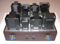
Just finished the build/re-build of my 300B push pull amplifier.
It would be interesting for the OP to temporarily test the amp with the outputs just being driven from the first stage with cap coupling. It sure isn't going to cope with the grid current, but it will still certainly work as an amplifier (a low gain one).
Sure, it would definitely work. It would be a completely different amplifier; I think we can agree on that. There are literally thousands of SN7-cap coupled-300B amps out there, no?
Thank you, and yes it is solid bubinga. It was called curly, which I'm sure is the same thing as waterfall. Had a great exotic hardwood source back in WI years ago. They have something from every country it seemed. I have designs built of teak, bubinga, zebrawood, cherry, and a few others I don't even remember.Is the case made of Waterfall Bubinga? Nice work.
I net it sounds glorious.
Sure, it would definitely work. It would be a completely different amplifier; I think we can agree on that. There are literally thousands of SN7-cap coupled-300B amps out there, no?
I mean skipping the 'SN7 input stage and going to the 46, so the use of a step up input transformer would be needed.
Got it. It sounded like audiowize was continuing to use the SN7.
I suppose that would be a reasonable attempt; grid leak current may be an issue with the smaller input transformers, which are typically not designed for any DC. Most PP interstage transformers can accommodate some DC.
There is no question in my mind that the miller capacitance will be extremely significant with the step-up operation; the source will be required to be capable of driving significant capacitance over the full frequency spectrum. Do the math, and make sure your source's output impedance is low enough.
Then there is the question if the transformer is adding impedance between source and miller capacitance, such that rolloff of the highs becomes an issue. Input transformers are not designed for any power delivery at all. This has been the entire reason I concluded with a 3-stage design with no first stage transformer; it is soooo difficult to get large signal swing to the 46 grid with a transformer. I have cap-coupled to the 46 because with consistency I failed to get low distortion with transformers. Even when I had the SN7 driving multiple types of IT, it was failure after failure.
- Status
- This old topic is closed. If you want to reopen this topic, contact a moderator using the "Report Post" button.
- Home
- Amplifiers
- Tubes / Valves
- Testing on latest PP 300B build