Just finished the build/re-build of my 300B push pull amplifier. Schematic attached. I was formerly using a very close build of Lynn Olson's Karna amp, using two interstage transformers. I had challenges getting the input stage right, due to the difficulty in the driving of the IT. I have since performed some testing of different topologies, and settled on the design here. It was the optimal way I found of getting lowest distortion to the driver stage.
Also, I modified the driver stage to fully differential, as it also provided excellent performance at 15W and below drive levels. Even at higher drive where some 300B grid current started to flow, I still had pretty good performance of the driver stage. Changing out my IT (I had tried a few brands) to the bifilar Monolith IT-02 gapped for push pull provided a few dB of lower odd distortion as well.
Output stage has pretty much remained as is, and has now become the limiting factor in the design. Not that I feel any need to improve it, but it's nice that I have given the output stage everything possible to provide low distortion.
Finally, I have resorted to using Rod Coleman's regulators in both DHT stages. They meet up to the hype; performance is repeatable; the DC voltage is rock steady, and "zero-point-zero" hum as a result. More commentary to follow in the next few posts: it will be better organized to separate data in individual posts.
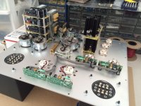
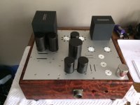
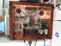
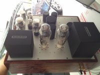
Basic build description is a single chassis for power supply, and mono block amps for signal path. DHT heating power supplies are incorporated into the mono blocks, as the initial build provided only a single 120VAC circuit for AC heating transformers. Happy to report that having the rectifier transformers in the mono blocks has been successful.
Everything is in the garage, so pictures are so-so, but you get an idea of the build.
I am interested in some commentary on the performance, as well as some assistance in taking meaningful measurements. I have decent hardware for measuring, but running Audiotester software has its challenges.
Also, I modified the driver stage to fully differential, as it also provided excellent performance at 15W and below drive levels. Even at higher drive where some 300B grid current started to flow, I still had pretty good performance of the driver stage. Changing out my IT (I had tried a few brands) to the bifilar Monolith IT-02 gapped for push pull provided a few dB of lower odd distortion as well.
Output stage has pretty much remained as is, and has now become the limiting factor in the design. Not that I feel any need to improve it, but it's nice that I have given the output stage everything possible to provide low distortion.
Finally, I have resorted to using Rod Coleman's regulators in both DHT stages. They meet up to the hype; performance is repeatable; the DC voltage is rock steady, and "zero-point-zero" hum as a result. More commentary to follow in the next few posts: it will be better organized to separate data in individual posts.
Basic build description is a single chassis for power supply, and mono block amps for signal path. DHT heating power supplies are incorporated into the mono blocks, as the initial build provided only a single 120VAC circuit for AC heating transformers. Happy to report that having the rectifier transformers in the mono blocks has been successful.
Everything is in the garage, so pictures are so-so, but you get an idea of the build.
I am interested in some commentary on the performance, as well as some assistance in taking meaningful measurements. I have decent hardware for measuring, but running Audiotester software has its challenges.
Attachments
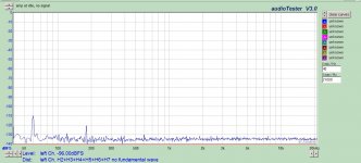
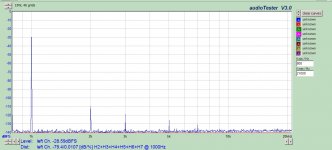
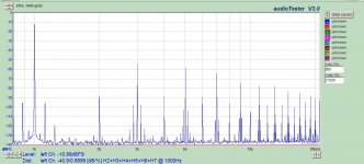
First, a shot of the output terminals with zero signal input. Very quiet, pleased to report. The 60 and 180 Hz shown here is actually a result of the rectifier transformers' magnetic field spilling into my measurement system. With shorted leads, I can actually produce this signal depending on the proximity to the transformers. It actually has little effect on the amp proper. Being in a garage with one bench, my test setup could use some improvement, but I have no issues with initial results like this. I have also attached my earlier design using AC heating, so you can see the improvement in noise at the output terminals. Three cheers for Rod's supply!
Attachments
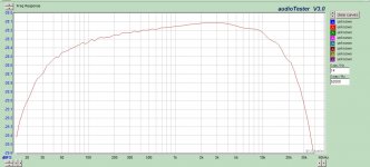
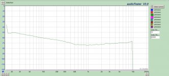
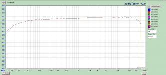
Frequency response and distortion. I know my distortion graph needs some help; haven't figured that out yet. Help is appreciated.
This amp will be driving speakers actively crossed over at the 80-120 Hz range, so I'm not too concerned about the low frequency behavior, but generally I'm pleased. -1 dB within 20 Hz - 30 kHz. Not too shabby for a no feedback design.
This amp will be driving speakers actively crossed over at the 80-120 Hz range, so I'm not too concerned about the low frequency behavior, but generally I'm pleased. -1 dB within 20 Hz - 30 kHz. Not too shabby for a no feedback design.
Attachments
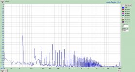
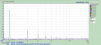
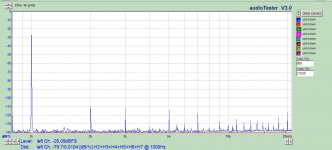
Performance at 1W into 4 ohm resistive load. The captions near the top of the image explains the conditions.
First is the speaker output. 0.02%. Note the sidebands around the fundamental are 120 Hz, which originates from the 250mV ripple present on the output stage B+. The input and driver stage have no ripple effect, as the input stage benefits from the CCS rejection, and the driver stage is shunt regulated with gas tubes.
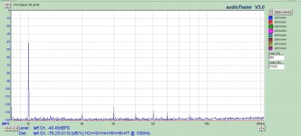
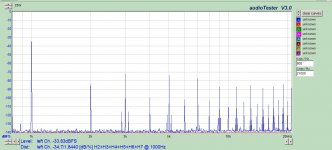
Next is the same conditions, but measurement is differential at the grids of the 46 triodes. This shows the input stage is doing a very fine job at 0.011%. Depending on the tube I use, I can improve the input stage performance. I have a few stellar SN7's that have been verified, and will use those when actually listening to the system. But for testing purposes I picked a good (not stellar) one.
Finally is the differential measurement at the grids of the 300B's. A little additional distortion has been added in the driver stage, but very minimal. I may experiment with matching pairs based on FFT and bias to try and improve the driver, but generally the triode connected 46 does a fine job.
First is the speaker output. 0.02%. Note the sidebands around the fundamental are 120 Hz, which originates from the 250mV ripple present on the output stage B+. The input and driver stage have no ripple effect, as the input stage benefits from the CCS rejection, and the driver stage is shunt regulated with gas tubes.
Next is the same conditions, but measurement is differential at the grids of the 46 triodes. This shows the input stage is doing a very fine job at 0.011%. Depending on the tube I use, I can improve the input stage performance. I have a few stellar SN7's that have been verified, and will use those when actually listening to the system. But for testing purposes I picked a good (not stellar) one.
Finally is the differential measurement at the grids of the 300B's. A little additional distortion has been added in the driver stage, but very minimal. I may experiment with matching pairs based on FFT and bias to try and improve the driver, but generally the triode connected 46 does a fine job.
Attachments
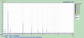
Performance at 15W into 4 ohm load. This will likely be my practical limit of output power, given my speakers and the volume level I listen to. Don't need rock concert levels, but I appreciate the power a few transients may require.
Again, speaker terminals, 46 grids, and 300B grids.
Input stage continues to operate very linearly, with friendly FFT spectrum and nonexistent higher order harmonics. Driver stage begins to add some higher order harmonics, but they are really really low given the signal drive level. Overall the result at the speaker terminals is pleasing; decent waterfall rolloff with low higher orders. Output stage seems to be holding its own at this point. The sidebands are annoying on paper, but I'm not about to regulate the B+, so it is what it is.
Attachments

Just for grins, ran it at 25W into 4 ohm load. Wanted to get a good idea of where the limiting factors are.
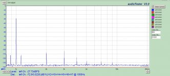
1.8% THD at the speaker terminals, significant clipping going on as indicated by the spray of high order and odds.
The signal at the 46 grids, however, is quite good, 0.01%. The input stage is happy getting pushed beyond what the amp is designed for.
The signal at the 300B grids is running into significant grid current, and the driver stage is running out of gas, 0.9%.
I may experiment a little to see at what point this hits the knee of the curve, but again, I have little intent to run the amp this hot. Perhaps modifying the bias conditions of the 300B stage could provide a little more headroom before the onset of grid current. It would be interesting to see how close to zero grid voltage I can run the differential driver stage before it falls apart.
Attachments
I'm assuming that these measurements are taken with a soundcard. What is the input bandwidth of the soundcard? What does the frequency response look like if you just test it in a loopback configuration?
I have found my cheap soundcard to be less than helpful for frequency response measurements. It just isn't capable of measuring outside the audio band. I use a signal generator and I sweep it.
The last amp I built has much wider bandwidth than the soundcard input both on the low and high end.
Edit: By the way, that looks like a very nice amp. Nice job.
I don't know the frequencyresponse of your input transformer but the 46 is probebly limiting the response (low and high) too.
Frequency response and distortion. I know my distortion graph needs some help; haven't figured that out yet. Help is appreciated.
This amp will be driving speakers actively crossed over at the 80-120 Hz range, so I'm not too concerned about the low frequency behavior, but generally I'm pleased. -1 dB within 20 Hz - 30 kHz. Not too shabby for a no feedback design.
I'm assuming that these measurements are taken with a soundcard. What is the input bandwidth of the soundcard? What does the frequency response look like if you just test it in a loopback configuration?
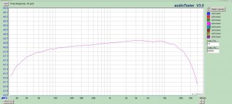
I suppose additional info would be warranted. Using a M-Audio Profire 610, which is 24/192 with balanced in and out. Also have an active differential probe with 1/10 and 1/100 settings. Most measurements are taken 1/100 to protect probe and sound card. I have the Profire set to 96 kHz sample rate for all measurements. Loopback result with diff probe at 1/100 inside the loop is included. I lose almost 0.3 dB at 20 Hz and maybe 0.05 dB at 30 kHz, so not all that bad.
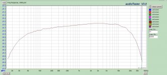
Also took loopbacks at the 46 grids, and another at the 300B grids. At the 46 I lose around 0.25 dB at 20 Hz, and maybe 0.5 dB at 30 kHz.
At the 300B grids I lose another 0.3 dB at 20Hz, and another 0.15 dB at 30 kHz.
Also, do you have a setup to measure Zout? I just use a beefy op-amp to drive a 50 Ohm resistor which drives the amp output. Then I just measure voltages and calculate Zout (It is a simple voltage divider at that point).
That's another measurement to consider doing.
Not currently, but I could make one up. Got a schematic?
I don't know the frequencyresponse of your input transformer but the 46 is probebly limiting the response (low and high) too.
Input transformer is not currently a part of the test system. It is only used when the source is unbalanced.
Attachments
Would load resistors added to Sec of Cinemeg IT and Monolith IT make any difference? Normally they are terminated so you get intended Pri impedance. If no load resistor it will depend on the input impedance of the stage, unless that is what you want? Just curious.
Last edited:
I just used a high current op-amp (I can't remember which but I could look at it when I get home). It just needs to be capable of handling current peaks of driving a 50 Ohm or so load. I wired it as a follower and drove it with a CD player at 2Vrms out. I powered it with plus and minus 5 V to keep power dissipation reasonable. I put a 50 Ohm resistor in series with the output of the op-amp, but there is no reason you couldn't use a higher resistance. It just becomes difficult to measure voltage on the output of the amp if the amp is noisy or if it has a very low Zout.
Then you just drive the output of the amp with the op-amp while the amp is muted.
I would then measure peak voltage at the output of the op-amp and peak voltage at the speaker terminal. Then you have a simple voltage divider and enough known values to calculate the Zout of the amp.
Then you just drive the output of the amp with the op-amp while the amp is muted.
I would then measure peak voltage at the output of the op-amp and peak voltage at the speaker terminal. Then you have a simple voltage divider and enough known values to calculate the Zout of the amp.
Would load resistors added to Sec of Cinemeg IT and Monolith IT make any difference? Normally they are terminated so you get intended Pri impedance. If no load resistor it will depend on the input impedance of the stage, unless that is what you want? Just curious.
Difference in frequency response? Possibly, but I don't feel any need to improve it to be honest. It is similar in response to Pete Millets' Fat Boy, possibly a little better.
"Fatboy" 300B Push-Pull Amp
I am more interested in minimizing distortion rather than getting +/- 0.01 from 10 to 100 kHz.
I have applied test load resistors to the IT secondary, with very little overall effect other than placing additional burden on the driver stage at the higher outputs. I have also noted that some pretty extreme zobel values are required to provide a nice square wave on the secondary of the input transformer. One of the mods I made from the first version was to have my balanced source directly drive the input stage, using the input transformer only as a balanced grid leak load. So effectively the input transformer is irrelevant to this amp's performance and sound. Should I ever require mating an unbalanced source to this amp, I might put a little effort into load resistors, but I don't see that happening at this point in time.
Any advice on how to configure AudioTester for distortion vs frequency, and IMD tests? What determines a good/bad result for IMD?
Hi,
I've built similar amps with PPP KT120s. I too connect the balanced input directly, using the input transformer secondary as a CT grid choke. Not to waste the input trannie I'm using the primary connection as a galvanically isolated output for my subwoofer. Works well and the single ended sub input doesn't unbalance my line stage output.
I've built similar amps with PPP KT120s. I too connect the balanced input directly, using the input transformer secondary as a CT grid choke. Not to waste the input trannie I'm using the primary connection as a galvanically isolated output for my subwoofer. Works well and the single ended sub input doesn't unbalance my line stage output.
Resistive load on interstage audio transformers in tube type amplifiers
What value of load resistor? According to Monolith IT-02 spec is 100K, so expected Pri impedance is about 100K for 40 (?). It added damping and therefore also reduce distortion. I can see 300B output distortion is a replica of 40, so maybe worthwhile to look more closely. For PP amp generally increased a bit of idle current can reduce distortion near cross-over, maybe to reduce 600 ohms shared cathode resistor .
What value of load resistor? According to Monolith IT-02 spec is 100K, so expected Pri impedance is about 100K for 40 (?). It added damping and therefore also reduce distortion. I can see 300B output distortion is a replica of 40, so maybe worthwhile to look more closely. For PP amp generally increased a bit of idle current can reduce distortion near cross-over, maybe to reduce 600 ohms shared cathode resistor .
Any advice on how to configure AudioTester for distortion vs frequency, and IMD tests? What determines a good/bad result for IMD?
Sorry, I can't help with AudioTester. I have done it in ARTA but there are several different types of IMD tests. You have to first decide which type you want to do. And there aren't many results on the net to compare your amp to (of zero-feedback tube amps, I mean). You could probably look around and find plenty of solid-state amps to compare to, though.
Judging by results other competent designers have gotten, I think you have done a very good job at optimizing this design.
If you want, here is another amp to compare measurements with, this one is my own zero-Gnfb amp (but it is a pentode output stage with cathode feedback with very little iron, so somewhat different): Tube Amps with a Twist: A Unity Coupled KT88 Amp with Plitron Transformers
Hi,
I've built similar amps with PPP KT120s. I too connect the balanced input directly, using the input transformer secondary as a CT grid choke. Not to waste the input trannie I'm using the primary connection as a galvanically isolated output for my subwoofer. Works well and the single ended sub input doesn't unbalance my line stage output.
Brilliant !
I have a DCX driving a 6 channel tube preamp, so don't need that setup, but I like your method very much. I suspect you need the sub input fairly close to the transformer, as they don't like capacitive loads?
Any reason for the switch to the Cinemag input transformer from the Tribute?
The Tribute I used was 1:1+1, so provided some gain that I did not require. Minor issue. It also was unshielded, which I consider quite important for an input transformer. Finally, the mounting configuration was not mechanically friendly to a simple installation, so required a subpanel and standoffs. Ultimately is was a combination of shielding and convenience that pulled me away from it.
To be fair, the Tribute had extremely high bandwidth with decent phase matching between sections, so it was a good performer. But the characteristics of the Tribute that were excellent were not a priority for me, whereas the characteristics of the Cinemag (or comparable Jensen) that were excellent were exactly what I needed. Either one would work well in this amp, I suspect, if one was using an unbalanced input.
The Cinemag has a mu metal shielded can, along with two internal electrostatic shields. Mounts from above the chassis with a single hole, so was convenient. Specs are good, too. Price is no comparison to the Tribute, somewhere between 2-3 times as much for the Tribute, when all I really needed was a high Z, low DCR grid choke that was convenient.
Like the electrical design, simple and direct, and performance looks very reasonable. The distortion spectrum is somewhat reminiscent of what I see in my own IT coupled GM70 SE amps, but obviously lower distortion overall than mine - I have a predominantly 2nd and 3rd with some 4th and 5th. I run through an input transformer (from balanced to unbalanced to the driver stage).
It's also the best sort of eye candy.. Nice job on all fronts.
It's also the best sort of eye candy.. Nice job on all fronts.
- Status
- This old topic is closed. If you want to reopen this topic, contact a moderator using the "Report Post" button.
- Home
- Amplifiers
- Tubes / Valves
- Testing on latest PP 300B build