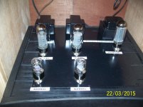
Hey guys, I am FINALLY almost done with my STEM amplifier. It is a school project based on the 6SN7 and 2A3. It is a headphone amp designed for 60-600 ohms. The amp sounds fantastic other than a nasty 60hz (I think) hum that I can't seem to get rid of. I am running the B+ as a regulated 21st century Maida Regulator, and the filament supplies for the 2A3 are Pete Millett Regulated Supplies.
Info:
1. The hum gets SUPER LOUD when I DISCONNECT the RCA cables from my amp or the DAC
2. The hum persists when I remove the input tube
3. I tried using a 2.5-0-2.5 transformer to supply AC to the tubes (paralleled) but it increased the hum
4. Shorting the output eliminates hum completely
5. Bottlehead crack plugged in to the same outlet produces 0 hum, so the issue isn't my mains line
6. When I connected the - part of the filament supply to ground instead of floating, the hum was reduced significantly, but the amplifier's volume was decreased significantly, which defeats the purpose of the amplifier
7. Adding/removing grid leak resistors had 0 effect.
8. I am running the amp without a potentiometer currently, but when I added a resistor on the input to simulate a pot, nothing changed
My schematic and grounding layout have been included
An externally hosted image should be here but it was not working when we last tested it.
An externally hosted image should be here but it was not working when we last tested it.
An externally hosted image should be here but it was not working when we last tested it.
An externally hosted image should be here but it was not working when we last tested it.
An externally hosted image should be here but it was not working when we last tested it.
An externally hosted image should be here but it was not working when we last tested it.
An externally hosted image should be here but it was not working when we last tested it.
An externally hosted image should be here but it was not working when we last tested it.
Last edited:
The construction is slightly different then the pictured layout, with the input jacks being grounded to a different location based on their current placement. Not sure if you can see much but ill try
An externally hosted image should be here but it was not working when we last tested it.
An externally hosted image should be here but it was not working when we last tested it.
An externally hosted image should be here but it was not working when we last tested it.
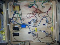
I see why you have HUM you need to tidy up your wiring you need to set the components out better have 1 single ground wire running from 1 side to the other connected to the mains earth so you can solder all components to ground on a common line. run a wire from 0 ohm tap from both OP Transformers to the common of your RCA inputs then at the volume pot ground the common ground to the single ground wire running from side to side that may help cut HUM!!! twist all heater wires tightly together and keep them away from any B+ power wires hope this helps
Last edited:
Looks like you're using the chassis itself as a ground plane. No wonder you have hum. You need to do this for RF projects where you need reactance out of the DC return path, and it doesn't matter since hum frequencies are way below the signal frequencies. At AF, that doesn't matter. DC returns should be made to a star or semi-star connection to get the capacitor recharge pulses out of the DC return, otherwise, they behave like another signal. Add in another ground loop between audio components, and it just gets worse. You also need to remember that this is a SE project, and the PSRR won't be as good as for a PP output stage.
A ground loop breaker between the DC neutral and the chassis also helps.
A ground loop breaker between the DC neutral and the chassis also helps.
The chassis isn't actually grounded. It is labeled as such, but it is not. I am using a wood chassis.
In response to mdamp, I believe I did this. I have traced out the ground wires in cyan. As you can see, the individual sections meet at local points, which then have twisted wires the meet up and merge in to one wire. This single wire is connected to a point on the PSU. This point is then connected to a local star (Instead of the configuration pictured, I have both wires for GND in the regulator connected to the top point). This star is under the heatsink, so you can't see it well in the picture, but this star is connected to the earth pin on the IEC, the negative of the filter cap, and the center tap of the power transformer.
In response to mdamp, I believe I did this. I have traced out the ground wires in cyan. As you can see, the individual sections meet at local points, which then have twisted wires the meet up and merge in to one wire. This single wire is connected to a point on the PSU. This point is then connected to a local star (Instead of the configuration pictured, I have both wires for GND in the regulator connected to the top point). This star is under the heatsink, so you can't see it well in the picture, but this star is connected to the earth pin on the IEC, the negative of the filter cap, and the center tap of the power transformer.
An externally hosted image should be here but it was not working when we last tested it.
An externally hosted image should be here but it was not working when we last tested it.
Last edited:
Also, the hum goes away immediately upon shutdown and it takes a few seconds before it settles in to a steady hum upon startup. I'm thinking it might be the supplies, even though I trust Pete's stuff, I feel like my grounding is fine.
I too had a problem with hum and it was a leaky power supply cap I replace them all and rewired the 6H9C/EL34 AMP I made onto a wooden board and wired in a common ground wire {see in pic} and then fired it up bit by bit meaning built the power amp side first {el34} powered it up no hum then built the preamp side and fired it up and wow no hum!!!
Attachments
It is normal for hum to take a few seconds to appear at startup as the tubes are still cold and not conducting yet. Of course it goes away immediately upon shutdown as there is no 60Hz power to make the hummm. I suggest the same: total rework of the wiring. Keep them short and twist any pair of wires. I see too many wires dangling. One hum problem i had was from a single long B+ wire dangling. Twisting it with a ground wire eliminates the hum.
From your picture it appears quite possible that there is a ground loop hum.
Wire all grounds to a single point, or use a bus.
All AC needs to be twisted. You shouldn't need AC on the 2a3 heaters if you do it well. There are many circuits floating around that show how to wire AC heaters for 2a3...
Lastly, do your heat sinks get hot? Is that a wooden board that they are below? Hope you understand my concern here...
The grounding scheme should be planned from the beginning. Once you start construction you should know where the ground point will be on the chassis and how the power supply capacitors will be grounded and how the signal grounds will be handled. Unfortunately, this takes experience and the primary motivation for gaining the experience is to be confronted with a situation like you find yourself in now.
I think that most experienced builders have their own techniques that work for them. There are various techniques, as has been expressed here, e.g., bus and star; but for me I keep all power supply grounds together and all signal grounds together and then run a single wire from each to the chassis ground. Notice that the RCA jack should be grounded with the signal grounds and should never be grounded to the chassis where it is mounted. Wiring should be direct and short whenever possible without big loops of wire flying about.
If you really want to learn proper building and grounding techniques, then this would be a great opportunity to learn. Start over; study your build and plan your grounds accordingly and remove all those big loops of wire and neaten the entire assembly. Ensure that all components are well mounted to tag strips and that none are floating with one end secured. You have an opportunity here to learn good construction techniques by starting over.
I tried to use star grounding. As pictured, the signal grounds for each side go to a star, then those 2 stars are connected where the twisted pair of ground wires meets. Then that is connected to the ground of the b+, which is then connected to a star with the power supply cap and the earth wire. My problem is that I don't know another grounding scheme that would make sense with my current layout to minimize noise. Is there any way you could help me design one that I could use and base my following builds off of? I thought I did a fine job but apparently not lol
Can you take a look at the pictures and see if you see any ground loop issue? I can't seem to locate it and honestly don't know of rewiring the whole amp will make a difference in the hum. If we can't solve the problem then I will rewire it but I'm not sure
Have a look at my amp I built all power on 1 side audio on the other side all neg side of caps resistors are on 1 ground wire, CT of power tranny is solder to the neg of power caps no HUM I had sooo much problem with hum I rewired my amp to this and now sounds bloody great with no hum just great upper and lower tones as it should sound!!
Attachments
So I should redo my whole chassis layout as well?
Well friend you do what you feel is right for you, You have HUM if you want to live with it great, all I can say is I redid my whole amp after reading many post from others that know way more then me and all that advise I read told me I had a grounding earth all wrong so again I took the advise and redid the amp from scratch and thanks all of those that know more then me as I have no hum now.
")
One more thing great made parts goes a long way too better sound as well what I do is build with good parts then once working to what I like sound wise I then replace parts with the best you can buy to get even better sound, and that is just me for me.
- Status
- This old topic is closed. If you want to reopen this topic, contact a moderator using the "Report Post" button.
- Home
- Amplifiers
- Tubes / Valves
- 2A3 Hum Problems in SE (Please Help!)