hi,
im trying to find the best operating points for the e182cc in dac output stage,
im using pcm1704 dac chip conectec to a pot. (volume control) and than straight to the grid of e182cc tubes through 1k resistor in series,
-grid resistor (to ground) at the moment is 360K.
-cathode resistor 330R
-anode voltage 220V
-current .around 13ma
....if you have any comments or suggestions please let me know.
best,k.
You have forgotten to state your anode resistance, and also if the tube is supposed to be working as a buffer or a amplifying stage.
If the latter, have you bypassed the cathode? This will give you more gain.
Anyway, the E182CC can handle some power, however I would use it quite conservatively. There is little point in running this tube that hard.
If the latter, have you bypassed the cathode? This will give you more gain.
Anyway, the E182CC can handle some power, however I would use it quite conservatively. There is little point in running this tube that hard.
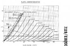
Attached is the specified operating conditions of Rl = 8k ohms, Ebb = 220V. You could choose an operating point anywhere along this 8k load line. I would stack a couple of 1.2V or 1.4V red LEDs as the cathode bias and expect the plate voltage to be about 100V with a plate current of about 12mA and Eg = -2.8V.
Attachments
Last edited:
....I.ve never bypassed cathode to ground resistor either with capacitor or LED....I will try that in future. Could you tell me why you prefer LED over cap as bypass. And what is the usual cap size ?
Can I use mkp or have to be electrolytic?
Best. And many thanx for your time.
Can I use mkp or have to be electrolytic?
Best. And many thanx for your time.
hi,
im trying to find the best operating points for the e182cc in dac output stage...
I would do this by optimizing/adjusting the bias while measuring the THD...
....I.ve never bypassed cathode to ground resistor either with capacitor or LED....I will try that in future. Could you tell me why you prefer LED over cap as bypass. And what is the usual cap size ?
Can I use mkp or have to be electrolytic?
Best. And many thanx for your time.
The LED is used to REPLACE the cathode resistor and its capacitor as it provides fixed bias for the tube while the resistor and cap provide self bias. For a good understanding of the importance of the cathode capacitor read this article by Lynn Olson. I prefer not to use a cathode capacitor since the best cap is no cap, so I use an LED for bias where possible. Use the best cap you can if you need to self bias the tube.
For a great education in AC and DC circuit theory along with tube theory read Valve Amplifiers by Morgan Jones.
You can determine best operating point of E182CC using this online simulator:
Triode Loadline Simulator v.0.6 (20140902 www.trioda.com)
Triode Loadline Simulator v.0.6 (20140902 www.trioda.com)
I tested that simulator. The results are quite identical with LTSpice, but this has some functional problem.
When you move the load line by adjusting supply voltage or max. current from their cursor, the THD remains unchanged.
To get the THD value of the new operating point you must (slightly) move the cursor at the top of the graph. Just then it calculates the new THD value.
When you move the load line by adjusting supply voltage or max. current from their cursor, the THD remains unchanged.
To get the THD value of the new operating point you must (slightly) move the cursor at the top of the graph. Just then it calculates the new THD value.
I explained this "phenomena" in the "Triode Loadline Simuator" thread. When you shift the external U/I markers, the operating point of a tube CHANGES automatically in such a way, that the bias voltage changes and voltage on the anode remains constant resulting that parameters used in calculating H2 changes in such a proportion that H2 remains unchanged. If you want to optimize the slope of a loadline for a given operating point, you should use internal markers. Then the operating point remains unchanged and you can see the influence of the loadline on the second harmonic distortion.
I understand your doubts. I have checked the lengths of graph sectors taken for the calculation of H2 under the debugger many times, and I compared them with hand-made graphs. It seems that it is OK (proportions of sectors used in calculations because of changing the operating point were preserved in spite of changing the loadline).
But I'm not infallible. I'll check exactly what is happening and I will try as soon as possible to confirm that it is OK or correct the error in calculations if I find them.
Thanks for your remarks.
But I'm not infallible. I'll check exactly what is happening and I will try as soon as possible to confirm that it is OK or correct the error in calculations if I find them.
Thanks for your remarks.
Hi,
External markers are those outside the x/y axis frame (white and light-blue), internal are those inside the box (yellow, dark blue).
Once you can the hang of it, it's really easy to use IME and quite accurate.
Also, keep in mind that the simulations are for resistively loaded circuits. Power tubes do not take the OPT into account so be ware.
Another thing to keep in mind is to go gently with some of the markers as the scripting can be rather long.
Cheers,")
I am not sure if I understood your explanation correctly.
External markers are those outside the x/y axis frame (white and light-blue), internal are those inside the box (yellow, dark blue).
Once you can the hang of it, it's really easy to use IME and quite accurate.
Also, keep in mind that the simulations are for resistively loaded circuits. Power tubes do not take the OPT into account so be ware.
Another thing to keep in mind is to go gently with some of the markers as the scripting can be rather long.
Cheers,
You can determine best operating point of E182CC using this online simulator:
Triode Loadline Simulator v.0.6 (20140902 [url]www.trioda.com)[/url]
I will do as soon as im back home. Away at the moment and can't use your software on my phone.
I will get back with my findings.
Thanx.
I do not notice that the following stage grid resistor is taken into account in the load line (e.g. post #7 from Palustris).
Referring to that graph, the equivalent load line with the second Rg in parallel would rotate slightly clock-wise round the operating point. This could decrease the available maximum peak of the plate signal enough (downward from 220V in this case) to introduce notable 2nd harmonic distortion. It would thus be advantageous to move the operating point to a lower voltage, still regarding fitting in the full plate swing down to 0V grid potential (in theory; somewhat further in in practice; tubes have a production spread!).
I have not used the Load Line Calculator; not sure if this is included there.
- Status
- This old topic is closed. If you want to reopen this topic, contact a moderator using the "Report Post" button.
- Home
- Amplifiers
- Tubes / Valves
- best operating points for e182cc tube