I tested that simulator. The results are quite identical with LTSpice, but this has some functional problem.
When you move the load line by adjusting supply voltage or max. current from their cursor, the THD remains unchanged.
To get the THD value of the new operating point you must (slightly) move the cursor at the top of the graph. Just then it calculates the new THD value.
I tried to explore the problem in this thread:
http://www.diyaudio.com/forums/tubes-valves/260908-triode-loadline-calculator-7.html#post4047611
At present program calculates harmonics mode detailed.
I do not notice that the following stage grid resistor is taken into account in the load line (e.g. post #7 from Palustris).
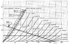
Referring to that graph, the equivalent load line with the second Rg in parallel would rotate slightly clock-wise round the operating point. This could decrease the available maximum peak of the plate signal enough (downward from 220V in this case) to introduce notable 2nd harmonic distortion. It would thus be advantageous to move the operating point to a lower voltage, still regarding fitting in the full plate swing down to 0V grid potential (in theory; somewhat further in in practice; tubes have a production spread!).
I have attached the plate curves again and added a following grid resistor of 470k and 270k to illustrate your point. 7.866k is the load line with the Rg = 470k and 7.77k Rg = 270k
Attachments
Thanks kindly, Palustris!
Although not quite - one needs to rotate the load line around the d.c. anode working point, not 220V. What you have shown is for different plate resistors of the values given, not an equivalent lower a.c. load. The plate still sits at - was it 100V originally - and the rotation of the load line round that point then moves the available positive peak plate voltage downward from 220V.
I may be accused of nit-picking with such a high next-stage grid resistor not having a large effect. If for illustration I may choose a different operating point - apology that I am unable to illustrate. If one chooses the rather more 'severe' case of a 12K plate load resistor with a next-stage grid bleed of 47K, then one firstly finds a convenient operating point at say Va=110V, Ia=12mA for the 12K load alone. (The relevant grid bias will be about -3,6V which does not concern us now.) Then, placing the 47K in parallel gives an equivalent (reduced) a.c. load of 9,5K rounded.
One must then draw a load line with a 9.5K slope through that Va=110V operating point. Looking at where the unloaded 12K alone cuts the Vg=0V curve gives 40V on my graph set. The theoretical available plate swing is then 40 to 250V or 210Vpp. Should one however look at a 9,5K equivalent load going through the operating point of 110V, 12mA, one now finds a lower limit of 45V where the Vg=0 curve is crossed, and only 205V where the new load line goes to the X-axis, representing an available Vpp=160V only.
This illustrates my point. In the second case the 2nd harmonic distortion will also be greater (one does not operate near the x-axis as rapid onset of 2nd harmonic distortion takes place there). I hope this makes it clear.
If you can again post a graph, my thanks!
hi,
thanx for all your replies, they make me move on a bit with me e182cc operating points and the triode loadline calculator is definitely a great thing, thanx.
i changed things around a bit and the sound at the moment is as good as never before. but im still open to your suggestions...if you have any comments about what i have done so far than please let me know.
my mains transformers are 230-0-230 ct. and each of them powers one e182cc output stage of my dac (dualmono psu).
clclrc filter with total resistance 10.7K - so thats Ra.
and that gives me 200vdc measured of total anode voltage for each tubes. and 100vdc for each triode.
all 4 cathode resistors are 300R (2 for each tube)
grid voltage measured 3.33vdc
current measured 0.011A
signal input resistor in series 1k
and grid leak resistor to ground 480k, i have used different values here but 470k-500k sound best to my ears and no cathode bypass capacitor. i have to mention that my dac has volume control between dac and tubes.
..i checked it with triode loadline calculator but the theory doesnt go along with practice here or im missing something?
..looking at triode calculator and setting it to my operating points it gives me cathode resistor of 350R...and my is only 300R ...and when i change it to 300R than the anode voltage, grid voltage and current are changing to lower values?
but it sounds great") ,..im happy to play around with it so please if you have any suggestions just go for it.
,..im happy to play around with it so please if you have any suggestions just go for it.
thanx.
thanx for all your replies, they make me move on a bit with me e182cc operating points and the triode loadline calculator is definitely a great thing, thanx.
i changed things around a bit and the sound at the moment is as good as never before. but im still open to your suggestions...if you have any comments about what i have done so far than please let me know.
my mains transformers are 230-0-230 ct. and each of them powers one e182cc output stage of my dac (dualmono psu).
clclrc filter with total resistance 10.7K - so thats Ra.
and that gives me 200vdc measured of total anode voltage for each tubes. and 100vdc for each triode.
all 4 cathode resistors are 300R (2 for each tube)
grid voltage measured 3.33vdc
current measured 0.011A
signal input resistor in series 1k
and grid leak resistor to ground 480k, i have used different values here but 470k-500k sound best to my ears and no cathode bypass capacitor. i have to mention that my dac has volume control between dac and tubes.
..i checked it with triode loadline calculator but the theory doesnt go along with practice here or im missing something?
..looking at triode calculator and setting it to my operating points it gives me cathode resistor of 350R...and my is only 300R ...and when i change it to 300R than the anode voltage, grid voltage and current are changing to lower values?
but it sounds great
,..im happy to play around with it so please if you have any suggestions just go for it.thanx.
Why not draw out your circuit on a piece of paper so we can understand it?
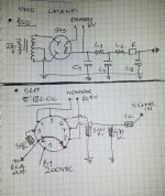
hi
i hope that will do.
psu = 2 chokes of 1.61k in total and 9.1K resistor = 10.71 k of Ra ....gives 200vdc (B+)
e182cc srpp
signal input from volume control,pot.
Attachments
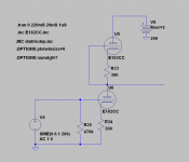
I drew up your SRPP in ltspice.
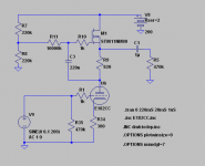
I did some SRPPs a few years back. The next step is to wire the top triode as a tube mu stage. Then to use a pentode as the top device instead of a triode.
Then to replace the pentode with a MOSFET - then you have a MOSFET gyrator plate load. I sugguest you try it out, it's only a few dollars of components and 15 minutes soldering. Put a small heat sink on the MOSFET.
With the gyrator, you can experiment and find the best OP point. Make R7 & R8 a trimmer pot, it will control your triodes plate voltage.
Attachments
...
..i checked it with triode loadline calculator but the theory doesnt go along with practice here or im missing something?
..looking at triode calculator and setting it to my operating points it gives me cathode resistor of 350R...and my is only 300R ...and when i change it to 300R than the anode voltage, grid voltage and current are changing to lower values?
thanx.
Take into account that the simulator is based on the averaged characteristics of the given tube type. It's aim is to replace the tedious step of finding a working point manually. The results of the measurements in a real system are usually different from simulation and, if necessary, should be revised during measurements. Moreover, if you exchange the tube to another one of the same type then voltages and currents in the real circuit can change. Results from simulator could help do find the starting point of experiments.
Congratulations, that the system keeps getting better
Confirming what Gsmok said.
One might say the practise doesn't go along with the theory! There is a manufacturing tolearnce in tubes of about 20% (more's the pity; I recall beter results in the heyday, but there it is.) I had variations of up to 50% on some new tubes, even for the triodes in the same bulb, and particularly those intended for computer duty - demands there are/were mostly for 'full on' and 'full off' and long life. Welcome to the new world of frequent mediocrity .... never mind.
Still one gets along. Where maximum voltage swing is desired with low distortion, one should have the plate operating point remain the same and juggle the cathode resistor to suit. For small signal use, the distortion results roughly point out the best operating area; not critical there.
If I have not said, thanks to Gsmok for this excellent 'tool'!
Last edited:
thats right, thanx to Gsmok for his amazing calculator and as he said its a great starting tool to enjoy different tubes. ...i've tried different operating points, voltages, resistors and blah blah blah,...and i have found my best op. points and im absolutely happy with it at the moment,...the sound is massive with 3d sound stage ...great top end and deep 3d bottom end. ...at the moment experimenting with different resistors and capacitors to get as much as possible out of my system..., quite like duelunds as output caps,...and takman mf resistors and shinkoh tantalums r not bad either but thats like adding some extra spices to your favourite meal just to make it taste better.....for now at least ...no one wants to eat the same meal everyday. . ...thanx for your help,...if you want to comment my op. points than feel free to do so, ..im not planning to add mosfet gyrator plate load for now...i like the simple srpp at the moment. best regards,. thanx.
...no one wants to eat the same meal everyday. . ...thanx for your help,...if you want to comment my op. points than feel free to do so, ..im not planning to add mosfet gyrator plate load for now...i like the simple srpp at the moment. best regards,. thanx.- Status
- This old topic is closed. If you want to reopen this topic, contact a moderator using the "Report Post" button.
- Home
- Amplifiers
- Tubes / Valves
- best operating points for e182cc tube